- Catalogs
- Brugg Pipesystems
- Biogas technology Flyer
- Company
- Products
- Catalogs
- News & Trends
- Exhibitions
Biogas technology Flyer
1 /24Pages

Biogas technology Flyer
1 /24Pages
Catalog excerpts

effective heating system for b/ogas-fermenterx Flexible solution*
Open the catalog to page 1
Fermenter equipment with BIOFLEX corrugated piping The helically corrugated BIOFLEX piping is the ideal solution through its simple and non-weld installation. Other advantages: - excellent corrosion resistance - highly flexible and self-compensating - far higher heat transfer than with conventional piping Installation - fast and convenient laying - simple pipe securing - non-weld connectors including through-connection through the tank wall For installation instructions and technical data: see Worksheets Biogas technology BGT.
Open the catalog to page 2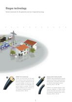
CALPEX® heat-insulated pipe CALPEX® can be laid direct into the trench with a minimum of work. Connections in the ground can largely be dispensed with. Due to its pre-insulation, the pipe has a high insulation coefficient. The advantage: energy loss is kept to a minimum. The desired length is delivered on site in one piece in a coil. Grouted or screwed connectors. Dimensions: DN 20 - DN 150 Extensive district heating networks PREMANT® plastic-sheathed piping is specially designed as a mains pipe for large-scale district heating networks. The properties: high insulation coefficient and leak detection...
Open the catalog to page 3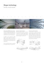
System package BRUGG fermenter heating In order to ensure optimal heat transfer to the substratum, the BIOFLEX CNW 60/66 (DN 50) corrugated pipe is fixed to the wall of the fermentation tank in one or more heating coils. In addition to the corrugated pipe CNW 60/66, the system package also includes the GRAPA connector system, the necessary wall through-connections including seals and the special brackets for securing the piping to the fermenter wall. There are two different options for connecting the corrugated pipes to the hot water mains: Connection inside the fermenter With the connection...
Open the catalog to page 4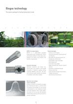
BIOFLEX corrugated piping BIOFLEX is a single-walled corrugated piping system made of stainless steel. The key constructional element of these pipes manufactured at our works in long lengths is the helically corrugated pipe. Connector technology Optimized connections and fittings enable the pipes to be coupled to all standard connections. A flameless graphite packing technology (GRAPA) is used here. This easy-to-fit connector system enables time-savings on installation work without welding. System advantages - surface up to 50 % higher maximum heat transfer through optimized wall thickness -...
Open the catalog to page 5
BIOFLEX Pipe systemBiogas Technology Type CNW End connector GRAPA-S incl. wall duct dia. 89 mm • Pleas note: the support type F (outlet) has to be installed 70 mm higher. • Gasket insert needs to be seated on the wall duct in full length. • For installation of the end connector see installation instruction. No. Type 2 End connector GRAPA-S DN 50 incl. wall duct dia. 89 mm 5 Gasket insert type A WD 85-94, core drilling dia. 150 mm 6 Fixing set incl. dowel BS 10 (brehole dia. 12 mm) 7 Through-/repair-connector/elongation GRAPA-S DN 50 (if necessary) 8 Installation tool for GRAPA-S...
Open the catalog to page 6
BIOFLEX Pipe systemBiogas Technology Type CNW End connector GRAPA-S incl. flange plate for steel- or concrete fermenter • Please seal flange plate pressure-tight to fermenter wall. • For installation of the end connector see installation instruction. • Please note: in case of wall < 120 mm please use special screws and dowels. • Please seal the thread with e.g. CURIL K2 sealing compound ist recommended by BRUGG. 2 End connector GRAPA-S DN 50 - R2 3 Elbow screw fitting DN 50 4 Double nipple R2with flange plate 300 x 300 x 3 mm 6 Gasket insert type Typ A WD 55-64, core drilling dia....
Open the catalog to page 7
BIOFLEX Pipe system Installation instructions Fermenter Installing the pipe work CNW 60/66, DN 50 with connector and seal 1 Installation of the BIOFLEX pipe work in a fermenter Measuring and marking the position of the pipe supports The height of the supports on the fermenter wall is determined by the position of the drill holes. The pipe work must lie axially to the core hole. Measure the height of all supports using a laser measuring device and drill the holes for them at intervals of c. 1.00 metre. Place the first and the last support at a distance of 1.3 m from the centre of the core hole....
Open the catalog to page 8
BIOFLEX Pipe system Installation instructions Fermenter Installing the pipe work CNW 60/66, DN 50 with connector and seal 7 The corrugated pipe is led out of the tank with the bending support (As described on Datasheet BGT 1.800) The BIOFLEX connector lies outside the tank. The welded-on wall duct lies inside the tank wall. For installation instructions for the leading out of the BIOFLEX pipe with its connector and gasket insert, see Figs. 10 to 47. Fitting the double nipple (pipe fitting) with flange plate Version for steel tanks or concrete tanks (also prefabricated) the shorter end points inwards...
Open the catalog to page 9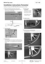
BIOFLEX Pipe system Installation instructions Fermenter Leading out the pipe work CNW 60/66, DN 50 with connector and seal 10 Position of the bending support relative to the core hole Important! The exact measurements must be observed to ensure that the wall duct is centrally aligned. 13 Bending the pipe out of the tank At least 4.5 m of loose pipe end is needed to introduce the pipe into the core hole. Attention! Make sure there is no kinking of the pipe! 14 Pushing in the pipe Push the pipe though the core hole as far as it will go. Support 11 The bending support 15 Securing the pipe to the...
Open the catalog to page 10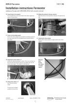
BIOFLEX Pipe system Installation instructions Fermenter Leading out the pipe work CNW 60/66, DN 50 with connector and seal 16 Fixing the pipe to the supports The corrugated pipe must now be fixed to the further supports by means of stirrup clamps. 20 Making the marking for the pipe connector Mark the position on the pipe before drawing it through into the tank. Inside of the tank Stirrup clamps Marking Stirrup clamp no. 4 17 Fixing it to the bending support Three of the stirrup clamps must be fixed to the bending support in the order shown here! The corrugated pipe lies along the plate in this...
Open the catalog to page 11All Brugg Pipesystems catalogs and technical brochures
 BRUGG-STAMANT Safety Pipe
14 Pages
 Spiramant Flyer
2 Pages
 Brugg Seminars
20 Pages
 Flexwell-LPG Piping
2 Pages
 Flexwell Safety pipe technology
32 Pages
 LMS 320 Monitoring device
2 Pages
 LMS 120 Monitoring device
2 Pages
 AdBlue Flyer
2 Pages
 Eigerflex Catalogue
25 Pages
 Premant Catalogue
70 Pages
 Casaflex catalogue
32 Pages
 Flexwell Catalogue
33 Pages
 Urbanflex
2 Pages
 CALPEX Leaflet
8 Pages
 CALPEX district heating pipe
56 Pages
 CALPEX PUR-KING
6 Pages
 COOLMANT
22 Pages
 COOLFLEX
27 Pages
 Datasheet Secon-X
2 Pages
 NIROFLEX Flyer
6 Pages
 Leak Monitoring Systems
8 Pages
 FLEXWELL-LNG Small Scale
4 Pages
 BRUGG-STAMANT Safety Pipe
2 Pages
 FLEXWELL-LPG
16 Pages
 SECON-X Brochure
20 Pages
 Hotelflyer
6 Pages
 Cooling Flyer
4 Pages
 Biogastechnik Flyer
13 Pages
 COOLMANT/COOLFLEX Flyer
8 Pages
 FSR Flyer
6 Pages
 SPIRAFLEX Brochure
6 Pages
 FLEXWELL FHK
6 Pages
 PREMANT Brochure
6 Pages
 CASAFLEX brochure
8 Pages
 FSR Brochure
32 Pages
 Datasheet PETREX
2 Pages
 EIGERFLEX Flyer
4 Pages
 CRYOFLEX
6 Pages


