Catalog excerpts

P R O D U C T D ATA Piezoelectric Charge Accelerometer Types 4326-A and 4326-A-001 Types 4326-A and 4326-A-001 are triaxial piezoelectric accelerometers with three independent outputs for simultaneous high-level measurements in three mutually perpendicular directions. The accelerometers feature the ThetaShear design and each transducing element is individually calibrated. The accelerometers have the same rectangular shape and 10–32 UNF connectors. The main differences between the models lie in the housing material, weight, temperature range and dielectric strength (flash over voltage). Uses and Features Uses General purpose vibration testing and analysis Multi-axis vibration and shock measurements Measurements in confined spaces Measurements in high-temperature environments Triaxial High sensitivity-to-weight ratio Low sensitivity to environmental factors Electrically insulated for ground-loop protection High resonance frequency Easily fitted to test objects using mounting clips Versions Table 1 Comparison of Type 4326 versions Housing Material Maximum Temperature Hard-anodized aluminium Description These piezoelectric accelerometers may be treated as charge sources. Their sensitivity is expressed in terms of charge per unit acceleration (pC/ms–2, pC/g). ThetaShear Design The ThetaShear design consists of a slotted cylindrical post holding a central seismic mass flanked by two piezoelectric plates. This assembly is clamped rigidly by the cover. To ensure optimum accuracy and reliability, molecular adhesion is the only bonding agent used to hold the assembly together. The ThetaShear design provides a combination of high measurement stability, excellent sensitivity-to-weight ratio and low sensitivity to
Open the catalog to page 1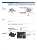
A remarkable feature of the principle behind ThetaShear is that the transverse resonance frequency is always outside the 10% frequency limit. This ensures minimum interference from orthogonal vibration components in the useful frequency range of the accelerometer. The ThetaShear design also provides excellent immunity to other environmental effects such as base strains, magnetic fields and acoustic fields. Fig. 1 Dimensions of Types 4326-A and 4326-A-001 Centre of gravity of accelerometer: 5.1 from mounting surface, perpendicular to the Z-axis Centre of gravity of seismic mass: 4.2 from...
Open the catalog to page 2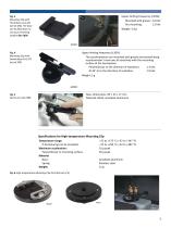
Upper limiting frequency (±10%): Fig. 3 Mounting Clip with Thick Base UA-1474 (set of 100). The base can be filed down to suit your mounting surface (far right) Mounted with grease: 2.0 kHz Dry mounting: 1.2 kHz Weight: 3.9 g Upper limiting frequency (±10%): Fig. 4 Mounting Clip with Swivel Base UA-1473 (set of 100) The accelerometers are mounted with grease and excited along accelerometer’s main axis of sensitivity with the mounting surface of the hemisphere: Perpendicular to the direction of excitation: 1.3 kHz At 45° to to the direction of excitation: 1.0 kHz Weight: 5 g Max. dimensions:...
Open the catalog to page 3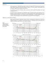
Calibration Each accelerometer is calibrated using random excitation and 1600-line FFT transformation to provide a high-resolution (amplitude and phase) frequency response. This yields a unique characterization and secures the integrity of your vibration measurements. The sensitivity given on the calibration chart is measured at 159.2 Hz with 95% confidence level using coverage factor k = 2. The upper frequency limits given on the calibration chart are frequencies where the deviation from the reference sensitivity at 159.2 Hz is within ±10%. The upper frequency limit is approximately 30% of...
Open the catalog to page 4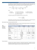
The calibration chart includes individual TEDS values that, together with a general formula, best fit the measured frequency response. The expression can be used for frequency response compensation in the specified frequency range. The relative frequency response, including amplitude and phase is: a f ----------j -----ln 10 f hp 1 1 f j ------- S rel ( f ) = ----------------------- × ---------------------- × ------------------------------------------------------ × f f f f 1 + j ------ 1 + j ----- 1 + j ------- 2 + j ------------ f ref f res f lp f hp Qf...
Open the catalog to page 5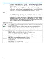
The electrical insulation of Type 4326-A comes from its fully hard-anodized common housing with insulation at the three cylindrical mounting holes. The hard-anodized mounting surfaces provide additional insulation. The electrical insulation of Types 4326-A-001 comes from the special mounting technique for the three sensing elements. A non-conductive glue is used to bond the sensing elements to the holes in the common housing. The three individually insulated sensing elements ensure that no ground-loop currents are induced in the measurement setup. This is particularly beneficial to engine...
Open the catalog to page 6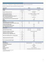
Specifications – Piezoelectric Charge Accelerometer Types 4326-A and 4326-A-001 All values are typical at 25 °C unless measurement uncertainty is specified Type Number General Weight Frequency Range (±10% limit) Mounted Resonance Frequency –2 Max. Transverse Sensitivity (at 30 Hz, 100 ms ) Transverse Resonance Frequency Max. Operational Continuous Sinusoidal Acceleration (peak) Electrical Residual Noise Level (measured with NEXUS Type 2692-001 in the specified frequency range) Capacitance (excluding cable) Case (signal ground) Insulation to Base Temperature Coefficient of Sensitivity...
Open the catalog to page 7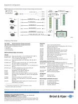
Equipment Configuration Fig. 8 Configurations for Brüel & Kjær’s family of triaxial charge accelerometers Female (F) Brüel & Kjær Conditioning Amplifier Overload * x = D (decimetres) or M (metres); yyy = length in decimetres or metres Please specify cable length when ordering CONDITIONING AND FRONT ENDS Type 3053-B-120 LAN-XI 12-ch. Input Module 25.6 kHz (CCLD, V) UA-2116-120 LAN-XI Front Panel, 12-channel Charge, 12 × 10–32 UNF (F) microdot connectors (Gain: 1 mV/pC) Type 3050-A-060 LAN-XI 6-ch. Input Module 51.2 kHz (Mic, CCLD, V) UA-2105-060 LAN-XI Front Panel, Charge Accelerometer,...
Open the catalog to page 8All Bruel and Kjaer catalogs and technical brochures
-
Data Analysis Software
6 Pages
-
B&K 2245 Sound Level Meter
8 Pages
-
HBK 2255 Sound Level Meter
10 Pages
-
Artificial Mastoid Type 4930
6 Pages
-
Power Amplifier Type 2718
2 Pages
-
DISCOM Mobile
6 Pages
-
DISCOM NVH Analysis Systems
4 Pages
-
TEDS Microphones
8 Pages
-
LDS V8
4 Pages
-
LDS Comet USB
4 Pages
-
LDS Laser USB
16 Pages
-
2690-A
16 Pages
-
4374
2 Pages
-
4152
4 Pages
-
4191
2 Pages
-
2719
2 Pages
-
LDS V8900
4 Pages
-
BKS 10
8 Pages
-
1704-A-001
4 Pages
-
4939
2 Pages
-
4138
4 Pages
-
4101-B and 4965-B
4 Pages
-
Sonoscout NVH Recorder
8 Pages
-
LDS Power Amplifiers
8 Pages
-
Type 2720
2 Pages
-
Type 2721
2 Pages
-
TYPE 3668
4 Pages
-
3656-A
4 Pages
-
TYPE 2270-S
28 Pages
-
LDS V994
2 Pages
-
TYPE 8702
16 Pages
-
BZ-7848-A
40 Pages
-
TYPE 9718-A:bp0317
12 Pages
-
TYPE 4720:bp1974
12 Pages
-
TYPE 4824:bp1936
4 Pages
-
SOUND LEVEL METER:bp 2025
28 Pages
-
Transducers and conditioning
188 Pages
-
Noise Sentinel Overview
3 Pages
-
Analyzer Catalogue
39 Pages
-
Noise Logger Type 3659
1 Pages
-
Sound level meters
17 Pages


