- Catalogs
- Brüel & Kjaer
- LDS V8900
LDS V8900
1 /4Pages

LDS V8900
1 /4Pages
Catalog excerpts

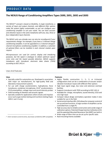
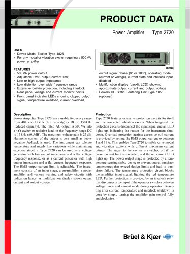
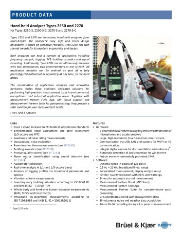
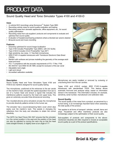
PRODUCT DATA LDS V8900 Shaker High-Force Electrodynamic Shaker The LDS® V8900 shaker is ideal for vibration and mechanical testing using sinusoidal, random or transient excitation. Systems are available in various forms to meet customers’ requirements, for example: Lin‐E‐Air trunnion‐mounted with a body rotation gearbox; combined with a horizontal hydrostatic slip table; silencer for shaker cooling fan; thermal management; quiet mode. V8900 Combo-Mounted Shaker with HBT Slip Table Trunnion-Mounted Shaker Specification (for combo performance contact your local Bruel & Kjaer representative) Performance Parameters Armature Diameter Sine Force (peak)* Lin-E-Air Body Resonance Overturning Moment Restraint Suspension Axial Stiffness Max. Acceleration (sine peak)* Suspension Cross-Axial Stiffness Suspension Rotational Stiffness Shaker Body Mass Total Weight Max. ½-Sine Peak Shock Force† with XPA88K Amplifier Effective Mass of Moving Element: 17 raised (hexagonal) inserts Velocity (sine peak)* 29 raised (hexagonal) inserts Full field Reduced field Usable Frequency Range ▪ Internal Load Support Capacity Recommended Amplifier * The force, velocity, and acceleration parameters detailed here are based on the shaker when driven by the recommended LDS XPA-K amplifier. † Random and shock ratings assume an m40 payload as specified by ISO5344; shock pulse 2 ms. ▪ Force will be reduced above 2200 Hz dependant upon payload and payload fixture dynamic response. Stray Magnetic Field:‡ ‡ Theoretic maximum, measured 150 mm (6 in) above table, full-f
Open the catalog to page 1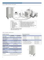
Typical V8900 Vibration Test System A F G A – Amplifier* B – Vibration Controller† C – Data Acquisition Unit† D – Pedestal Control Unit†‡ E – Shaker Hydraulic Pump* F – Accelerometer(s) G – V8900 Shaker H – Cooling Fan Starter Box* I – Cooling Fan 1 – Vibration drive signal from vibration controller to amplifier 2 – Feedback signal from accelerometer(s) on armature/payload 3 – Oil supply (and return) for V8900 hydrostatic bearing 4 – Cooling fan on/off control from pedestal control unit CANbus 5 – CANbus between amplifier and pedestal control unit 6 – Armature drive power, field and degauss coils...
Open the catalog to page 2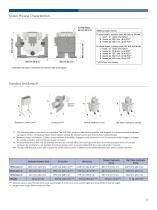
Shaker Physical Characteristics 17 raised inserts, stainless steel, M8, M10, or 3/8 UNC 1 insert at centre of armature 8 inserts on 203.2 mm (8 in) PCD** 8 inserts on 406.4 mm (16 in) PCD** 29 raised inserts, stainless steel, M8, M10, or 3/8 UNC 1 insert at centre of armature 4 inserts on 101.6 mm (4 in) PCD** 8 inserts on 203.2 mm (8 in) PCD** 8 inserts on 304.8 mm (12 in) PCD** 8 inserts on 406.4 mm (16 in) PCD** ** PCD = Pitch Circle Diameter # Dimension with body in mid-position and includes height of jacking pads. Standard Ancillaries†† optional silencer Pedestal Control Unit‡‡ Shaker Hydraulic...
Open the catalog to page 3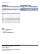
System Specification Electrical and Compressed Air Supply Environmental Data Working Ambient Temperature Range: Total Electrical Requirements: amplifier, FPS, fan, and ancillaries (steady state) Maximum Acoustic Noise at 1 m (3.3 ft) Distance:* Shaker Total Heat Dissipation: Shaker to Air (from body) Cooling Airflow: Shaker via Cooling Fan Complies with the following EU directives: –– Machinery: 2006/42/EC –– Low Voltage: 2014/35/EU –– EMC: 2014/30/EU –– Designed in accordance with EN 61010-1:2010 © Brüel & Kjær. All rights reserved * Maximum acoustic noise levels do not take into account any...
Open the catalog to page 4All Brüel & Kjaer catalogs and technical brochures
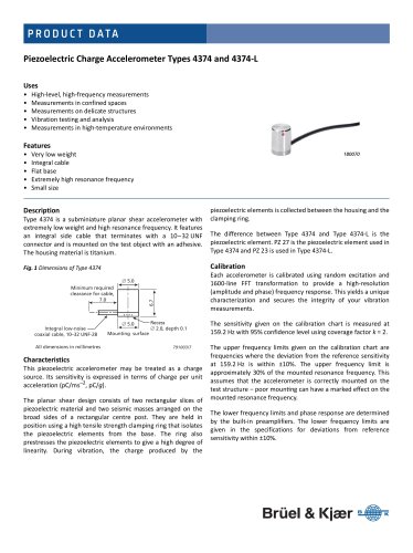
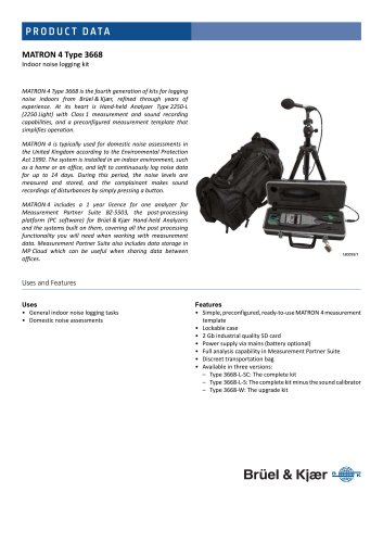
 Artificial Mastoid Type 4930
6 Pages
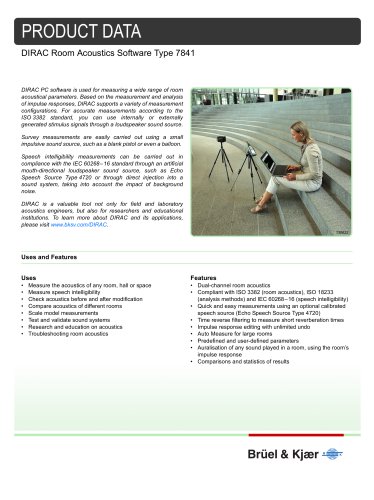
 Power Amplifier Type 2718
2 Pages
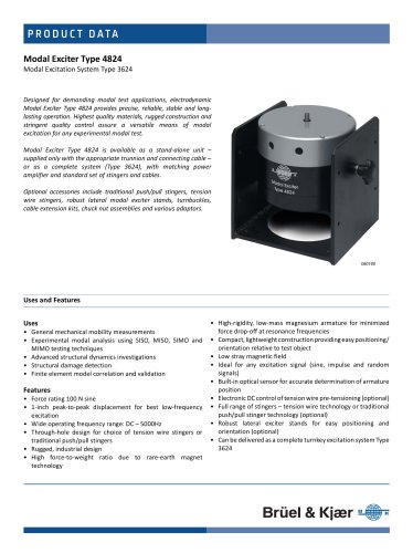
 DISCOM Mobile
6 Pages
 DISCOM NVH Analysis Systems
4 Pages
 TEDS Microphones
8 Pages
 LDS V8
4 Pages
 LDS Comet USB
4 Pages
 LDS Laser USB
16 Pages
 2690-A
16 Pages
 4374
43742 Pages
 4326-A-001
8 Pages
 4152
41524 Pages
 4191
41912 Pages
 2719
27192 Pages
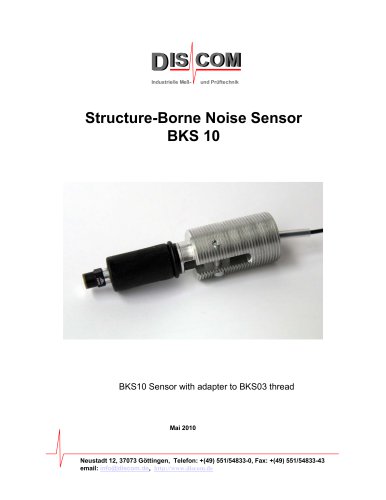 BKS 10
8 Pages
 1704-A-001
4 Pages
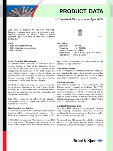 4939
49392 Pages
 4138
41384 Pages
 4101-B and 4965-B
4 Pages
 Sonoscout NVH Recorder
8 Pages
 LDS Power Amplifiers
8 Pages
 Type 2720
2 Pages
 Type 2721
2 Pages
 TYPE 3668
4 Pages
 3656-A
4 Pages
 TYPE 2270-S
28 Pages
 LDS V994
2 Pages
 TYPE 8702
16 Pages
 BZ-7848-A
40 Pages
 TYPE 9718-A:bp0317
12 Pages
 TYPE 4720:bp1974
12 Pages
 TYPE 4824:bp1936
4 Pages
 SOUND LEVEL METER:bp 2025
28 Pages
 Transducers and conditioning
188 Pages
 Noise Sentinel Overview
3 Pages
 Analyzer Catalogue
39 Pages
 Noise Logger Type 3659
1 Page
 Sound level meters
17 Pages


Archived catalogs
 B&K 2245 Sound Level Meter
8 Pages
 HBK 2255 Sound Level Meter
10 Pages
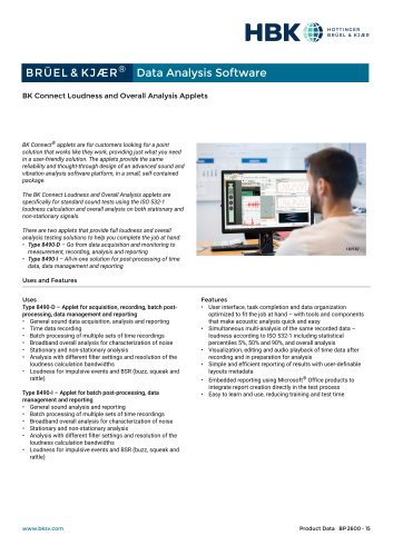 Data Analysis Software
6 Pages
- Power supply unit
- DC power supply
- AC/DC power supply
- Brüel & Kjaer calibrator
- Analog I/O
- Single-output power supply
- Digital indicator
- Portable analyzer
- Communication gateway
- Measurement software
- Brüel & Kjaer signal amplifier
- Turntable
- Tabletop power supply
- Piezoelectric accelerometer
- Real-time analyzer
- Tilt sensor
- Laboratory analyzer
- Ethernet gateway
- Automated software