

LEDO

LEDO
Before installation, ensure the power supply is isolated. Connect the unit as required. Set the 'Range' to the desired position for seconds, minutes, or hours. Adjust the 'Set %' to the required percentage of the selected range. Apply power across terminals 'A1' and 'A2'. The green LED will flash, indicating timing in progress. The relay remains de-energized initially, with contacts 15/16 closed and 15/18 open. After the delay period, the relay energizes, contacts change state, and the red LED illuminates. The green LED stays lit. To repeat the timing process, remove and reapply power.
Supply voltage ranges from 12 to 230V AC/DC with a frequency range of 48-63Hz. The unit supports a supply variation of +/- 15% and is rated for overvoltage category III. Power consumption varies by voltage, with maximums of 3.4VA for AC and 0.95W for DC. The timing function is a Delay On Operate with seven selectable ranges from 0.1 seconds to 100 hours. Reset time is 100ms, with accuracy within ±1% of the full scale. The unit operates within an ambient temperature range of -20 to +60°C and relative humidity up to 95%. The output is a SPDT relay with a rating of 250V 8A for AC1 and 25V 8A for DC1. Electrical life exceeds 150,000 operations at rated load.
The unit features a green LED for power and timing indication and a red LED for relay status. It is housed in orange flame-retardant material and mounts on a 35mm DIN rail or directly via screws. Terminal protection is rated to IP20. Dimensions are provided for installation, with specific instructions for surface mounting.
The unit conforms to IEC 61812 standards and is CE, C-tick, and RoHS compliant. It meets EMC immunity and emissions standards as per EN 61000-6-2 and EN 61000-6-4.
Catalog excerpts
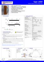
Type: LEDO Delay On Operate, Multi-voltage Timer Terminal Protection to IP20 *NEW* 17.5mm DIN rail housing Supply Initiated Delay On Operate timing function 7 Selectable time ranges (0.1 seconds – 100 hours) Fine adjustment of selected time range Multi-voltage input (12 – 230V AC/DC) 1 x SPDT relay output 8A Green LED indication for supply / timing status Red LED indication for relay status Conforms to IEC 61812 FUNCTION DIAGRAM TECHNICAL SPECIFICATION Supply voltage U (A1, A2): Frequency range: Supply variation: Overvoltage category: Rated impulse withstand voltage: Power consumption (max.): AC: DC: Timing function: Timing ranges (7): Reset time: Accuracy: Adjustment accuracy: Repeat accuracy: Drift with temperature: Drift with voltage: 100mS ± 1% of maximum full scale < 5% of maximum full scale ± 0.5% at constant conditions (IEC 61812) ± 0.05% / °C ± 0.2% / V Power on indication / Timing1: Relay status Ambient temp: Relative humidity: Output (15, 16, 18): Output rating: SPDT relay AC1 AC15 DC1 ≥ 150,000 ops at rated load 2kV AC (rms) IEC 60947-1 4kV (1.2/50µS) IEC 60664 BEFORE INSTALLATION, ISOLATE THE SUPPLY. Connect the unit as required. Installation work must be carried out by qualified personnel. Electrical life: Dielectric voltage: Rated impulse withstand voltage: Setting the unit. • Set the “Range” to the required position (depending on whether seconds, minutes or hours are required). • Set the “Set %” adjustment as required. The “Set %” is a % of the selected range; so for example, a 30% setting on the 1 – 10 hour range will give 3 hours. Housing: Weight: Mounting option: Terminal conductor size Orange flame retardant UL94 ≈ 60g On to 35mm symmetric DIN rail to BS EN 60715 or direct surface mounting via 2 x M3.5 or 4BA screws using the black clips provided on the rear of the unit. ≤ 2 x 2.5mm2 solid or stranded Applying power. • Apply power across terminals “A1” and “A2” and the green LED will start flashing indicating timing in progress. • The relay will remain de-energised (contacts 15 / 16 closed and 15 / 18 open) and red LED extinguished. • After the delay period “t” has elapsed, the relay will energise (contacts 15 / 16 open and 15 / 18 closed) and the red LED will illuminate. • The green LED will remain permanently lit. • The whole timing process is repeated by removing and re-applying power. Conforms to IEC 61812. CE, C-tick and RoHS Compliant. EMC: Immunity: EN 61000-6-2 (EN 61000-4-3 10V/m 80MHz - 2.7GHz) Emissions: EN 61000-6-4 In accordance with IEC 61812, the green LED is permitted to extinguish during a voltage dip or momentary interruption of the power supply providing the state of the output relay does not change. The dip / interruption duration and levels are defined in the product standard. SETTING DETAILS 1. Power supply status / Timing (Green) LED 2. Relay output status (Red) LED 3. “Set %” adjustment 4. Time delay “Range” selector Insert screwdriver to release clips CONNECTION DIAGRAM Withdraw clips fully when surface mounting Broyce Control Ltd., Pool Street, Wolverhampton, West Midlands WV2 4HN. England Tel: +44 (0) 1902 773746 Fax: +44 (0) 1902 420639 Email: [email protected] Web: www.broycecontrol.com The Information provided in this literature is believed to be accurate (subject to change without prior
Open the catalog to page 1All Broyce Control catalogs and technical brochures
 CONTROL RELAYS
4 Pages
 EARTH LEAKAGE RELAYS
4 Pages
 P9600 Shortform
4 Pages
 P50 shortform
4 Pages
 TIMERS
4 Pages
 THREE PHASE RELAYS
4 Pages
 BHRM
BHRM1 Page
 LEIN
LEIN1 Page
 LRTM/2
1 Page
 LART
LART1 Page
 LMMT
LMMT1 Page


- Transformer
- Dry transformer
- Protection relay
- Current transformer
- Encapsulated transformer
- Monitoring relay
- Voltage protection relay
- DIN rail mount transformer
- Relay module
- DIN rail protection relay
- Three-phase protection relay
- Toroidal transformer
- IEC protection relay
- DIN rail time relay
- Programmable protection relay
- DIN rail monitoring relay
- Panel-mount protection relay
- Earth-leakage protection relay
- Protection transformer
- VirtualExpo Group
- Our Partners
- Recruitment
- Testimonials