
- Catalogs
- Brodersen Controls
- Data Radios Data Sheet

Data Radios Data Sheet

Data Radios Data Sheet
Catalog excerpts
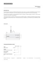
The UCW-50.924 is designed as a SRD (Short Range Device) radio modem in accordance with EN300 220. It fulfils all nationaland EU regulations with regard to radio-technical approval as well as with regard to EU conformity (CE Marking).The electronics are installed in a housing designed for DIN rail mounting. The supply voltage is 24-48V DC. 6 LEDs provideinformation on the status of the equipment.A RS-232/V24 interface is available as interface that works with 9600 baud (8N1). 1200 Bits/s and 2400 Bits/s (standard setting)are available as ғdata transmission rate. The switching frequency for 1200 Bits/s is at 1200/1800 Hz and for 2400 Bits/s at 1200/2400 Hz. UCW-50.924 > Radio ModemUCW UCW-50.924 /xx Type Output 500mW transmission power50 Power Supply 24-48V DC924 Specific Setup Parameters xxxx > Brodersen Controls A/S * Industrivej 3 * DK-4000 Roskilde * Denmark * Tel (+45) 4674 0000 * Fax (+45) 4675 7336 40047 100/01.08 size="-1">
Open the catalog to page 1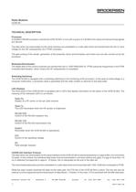
Processor A HC68HC705C8A processor controls the UCW-50.924. It runs with a quartz of 4.00 MHz from where all internal timing signals are derived.The data which are downloaded via the serial interface are embedded in a radio data frame and transformed into the LF drivevoltage for the S/E subassembly via a FFSK modulator.The gate pulsing of the sender, generation of the preamble, block synchronisation and check sum are also carried out by theprocessor. Modulator/Demodulator The digital data of the control computer are transformed into in 1200/1800/2400 Hz FFSK subcarrier frequencies in the FFSK...
Open the catalog to page 2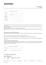
Physical Structure of the Radio Data Stream If the UCW-50.924 receives data via radio, these are sent out of the serial interface if the CRC and the address parameters havebeen checked. As no control characters are used for interface protocols, the complete binary character set 00 Hex to FF Hex is available as effective characters. Hereby, the UCW-50.924 acts like a V24/RS232 line with delay time. If this delay time is taken into account, any chosen protocols can be run (ACK/NAK, Polling-Selecting, Modbus, Siemens SPS etc.). The radio data telegram consists of an unmodulated carrier gate pulsing...
Open the catalog to page 3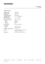
Operating mode: Semiduplex. Frequency range: 430-470 MHz. HF channels: Up to 64. Transmission power: Pout = 500mW . Channel bandwidth: 12,5 kHz, 20kHz, 25kHz. Modulation type: FFSK. Data rate transmission: 2400 (1200) bits/s. RS-232 Interface Level: Voltage supply: V24 (+ / - 3 to 12 V).Inputs:RxD, RTS. Outputs:TxD, CTS. Data rate:9600 Bits/s. Data format:8/N/1. 24-48V DC (20-60V DC). Current input: Operating temperature range: Reception:<50mA. (24V DC) Send:<1000mA. (24V DC) - 20 C to + 70 аC. Housing: Anodized aluminium with plastic ends.According to DIN 43880. Dimensions :HxWxD: 80(+connectors)x162x62mm....
Open the catalog to page 5
The UCW-24/28IO/50 is a general-purpose wireless remote I/O module, widely used in industrial monitoring and control, water and effluent treatment plants, pipeline monitoring, and other applications where long distances or other obstacles make it difficult or uneconomical to use wire communication. The Basic Module has 16 digital inputs, 8 digital outputs, and optionally 4 analog inputs. The I/O capacity of a Basic Module can be expanded by adding one or more Expansion Modules connected through a Local Bus. Its DIN rail mounting enclosure and plug-in screw terminal blocks make it easy to install...
Open the catalog to page 7
Frequency Range: 440.000 470.000 MHz:Product designation:HFT-700Output Power:0.1 ֖4 W Product Description:Land Mobile Service Registration Number:E811063M-EOMarking:CE 0682 (!) Caution! Products that are marked with the symbol (!) did not have uniform European certification at the time of preparation of this document. They should therefore be used according to prevailing local regulations with regard to frequency, transmittingpower, operating limitations, etc. > Mechanical Details The external dimensions of the UCW-24/28IO/50 conform to DIN 43880, making it suitable for standard DIN rail installa-...
Open the catalog to page 8
The total number of inputs and outputs of an UCW-24/28IO/50 node depends on the Expansion Modules used in addition tothe Basic Module. Up to 8 Expansion Modules can be connected to one Basic Module, through the Local Bus connectors (RJ- 45 type). The following Expansion Modules are available: Using Expansion Modules UCL-16DI.D1:16 digital inputs Օ UCL-32DI.D1:32 digital inputs UCL-08AI.D1:8 analog inputs Օ UCL-08DO.R1:8 digital relay outputs UCL-16DO.P1:16 digital solid-state switch (open-collector) outputs Օ UCL-04.AO.D1:4 analog outputsWhen adding Expansion Modules, they should be connected...
Open the catalog to page 10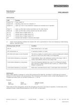
LED FunctionsLEDFunction System PwrPower supply onSystem OKOperating mode and error indication (*)System I/OLights up if one or more expansion modules are connected and in operationRadio TxLights up while data is being transmitted over the radio channelRadio RxLights up while data is being received over the radio channelA0...A7Indicate status of digital inputs 1-8B0...B7Indicate status of digital inputs 9-16C0...C7Indicate status of digital outputs 1-8RFIndicates field strength of received radio signal(*)Under normal operating conditions the System OKӔ LED is permanently lit. Errors are indicated...
Open the catalog to page 11
Each of the 16 internal digital inputs has a counter and a timer function available: i.e., up to 16 event counters and timers arepossible in a single UCW-24/28IO/50 Basic Module. A 16-bit register containing the counter/timer value is assigned to each input. The first counter/timer register is assigned to Input 0 (Port A) and the last counter/timer register to Input 15 (Port B). Counter / Timer Counter If an input has been configured as a counter, pulses (each consisting of a logic high plus a logic low transition) at the input arecounted. This feature can be used to measure outputs of pulse...
Open the catalog to page 12
If analog inputs exist in an UCW-24/28IO/50 node, either in the Basic Module or in one or more Expansion Modules connected to it, the minimum, maximum, and average values are automatically determined for the first 4 analog inputs.An averaging period of 60 seconds is set in the UCW-24/28IO/50 at the factory, before delivery. The user can change thisaveraging period, by altering the contents of the control register 919. A value of 0 in effect disables the averaging function.The 60-second averaging period results in a running time of 2 years, given the Units memory capacity. If this period isexceeded,...
Open the catalog to page 13All Brodersen Controls catalogs and technical brochures
 UDC-32
4 Pages
 UDC-35
4 Pages
 Signal Converters & Isolators
19 Pages
 Power Supplies
3 Pages
 Operator Interfaces
12 Pages
 Power Supplies
8 Pages
 PX Signal Converters
6 Pages
 igital timer eliro
3 Pages
 control & monitoring relays
35 Pages


Archived catalogs
 Data Radios Sales Brochure
4 Pages
 X Timer data Sheet
31 Pages
 Data Radios Sales Brochure
4 Pages
 RTU870 Selection Guide
6 Pages
 RTU870 Data Sheet
39 Pages
 RTU32 Data sheet
9 Pages
 RTU Overview Brochure
2 Pages
 RTU32 Sales Brochure
8 Pages


- Display module
- DC power supply
- AC/DC power supply
- Digital indicator
- Switched-mode power supply
- Panel panel meter
- Electronic display panel
- DIN rail power supply
- Information display
- DIN rail converter
- Regulated power supply
- LCD operator terminal
- Process panel meter
- Illuminated indicator
- Monitoring relay
- Position indicator
- Temperature indicator
- VirtualExpo Group
- Our Partners
- Recruitment
- Testimonials