- Catalogs
- Brevini Power Transmission
- VPS Mobile Valves
- Products
- Catalogs
- News & Trends
- Exhibitions
VPS Mobile Valves
1 /68Pages

VPS Mobile Valves
1 /68Pages
Catalog excerpts

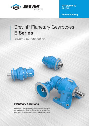
Motion Systems Technical Catalogue
Open the catalog to page 1
© 2018 Dana Brevini S.p.A. all rights reserved. Hydr-App, SAM Hydraulik, Aron, Brevini Hydraulics, BPE Electronics, VPS Brevini, OT Oiltechnology, logos are trademarks or are registered trademarks of Dana Brevini S.p.A. or other companies Dana in Italy and other countries. The technical features supplied in this catalogue are non binding and no legal action can be taken against such material. Dana Brevini will not be held responsible for information and specifications which may lead to error or incorrect interpretations. Given the continuous technical research aimed at improved technical features...
Open the catalog to page 3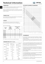
Motion Systems INTRODUCTION OIL VISCOSITY ACCORDING TO TEMPERATURE Read this instructions carefully before installation. All operations must be carried out by qualified personnel following the instructions. The user must periodically inspect, based on the conditions of use and the substances used, the presence of corrosion, dirt, the state of wear and correct function of the valves. HYDRAULIC FLUID Use only mineral oil (HL, HLP) according to DIN 51524. Use of other different fluids may damage the good operation of the valve. VISCOSITY The oil viscosity must be in the range of 10 mm2/s to 500...
Open the catalog to page 4
Motion Systems Table 2: Reccomanded contamination level.
Open the catalog to page 5
Motion Systems MAIN CHARACTERISTICS GENERAL CONDITION OF WORK All the production Dana Brevini want to be a high quality production. Infact the project of each single valve and the choice of the better materials, machined with the highest tecnologies and under the strongest controls in each process, allow highest characteristics and numerous applications described in the following pages. Furthermore: (!) threads availables on request (2) threads availables on requestsolo only for outlet side (3) inlet section with top output (4) output section with standard upper thread + carry over (see...
Open the catalog to page 6
Motion Systems OVERALL DIMENSIONS MONOBLOCK Type
Open the catalog to page 7
CHARACTERISTIC PRESSURE DROP FLOW CURVES Inlet pressure drop between P spool in central position Inlet pressure drop between P A (B) spool in working position N.o sections Inlet pressure drop between A (B) spool in working position Metering curves are different for each typee of spool. Therefore particular curves are supplied on request The curves are obtained using standard double acting spool (cod. ST1) with oil at 50°C and viscosity 36 mm² / s 6
Open the catalog to page 8
Motion Systems OVERALL DIMENSIONS MONOBLOCK Type
Open the catalog to page 9
CHARACTERISTIC PRESSURE DROP FLOW CURVES Inlet pressure drop between P spool in central position Inlet pressure drop between P A (B) spool in working position psi bar 24 Inlet pressure drop between A (B) spool in working position Metering curves are different for each typee of spool. Therefore particular curves are supplied on request The curves are obtained using standard double acting spool (cod. ST1) with oil at 50°C and viscosity 36 mm² / s 8
Open the catalog to page 10
Ordering code Inlet section Outlet section Working sections (repeat for any section) N.o working sections Inlet type Valves arrangement Main relief valve setting Positioning / Control side B Service port valves Overload valve setting Hand lever Working section repeated for n. times (1) Optional fields. Not specify if not required. (2) Service port valves optional, is required a special monoblock body. HYDRAULIC SCHEME Working sections Inlet section Outlet section Side B (Positioning / Control) Outlet section
Open the catalog to page 11
Ordering code ^ Motion Systems ORDERING CODE EXAMPLE 004 - Direct main relief valve + Solenoid dump valve 24V N. Open CS1 - Spool control side A D4 - Spool control side B, 3 pos. spring centred spool, detent in "b" VB1(150) - Overload valve in position "B" - Setting 150 bar W2 - Standard handle lever X2 - Working section repeated for n. 2 times ST1 - Spool, 3 position, double acting CS1 - Spool control side A D4 - Spool control cap side, 3 pos. spring centred spool, detent in "b" W2 - Standard handle lever
Open the catalog to page 12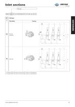
Motion Systems (1) On request. RIGHT inlet section with top inlet (IDT). Contact our sales department. (2) On request. RIGHT inlet section with side inlet (IDL). Contact our sales department.
Open the catalog to page 13
Motion Systems Valves choice MONOBLOCK -'] Valves arrangements and main - relief valve setting DCV40 (!) Specify pressure relief valve setting (from 20 to 400 bar). In the order it is suggested specify the flow rate. (2) Include block (DCV40 ) and special monoblock body
Open the catalog to page 14
Motion Systems 3 position, double acting 3 positions, single acting in A - A open 3 positions, double acting, - Lc blocked - A and B open 3 positions, single acting in B - B open 3 positions, double acting, - Lc blocked - A and B blocked 3 positions, double acting regenerative in A (not standard) 3 positions, double acting, - A and B open 3 positions, double acting regenerative in B (not standard) 3 positions, double acting, - A open - B blocked 4 positions, double acting with 4th float position 3 positions, double acting, - A blocked - B open 2 positions with function dead man (unactivated) in...
Open the catalog to page 15
Spool control side A BREVINI Motion Systems CS** Spool control side A Description Standard handle (1) CSA. = Aluminium version (only DCV40)
Open the catalog to page 16
Motion Systems | CS** | Spool control side A Description Drawing Safety handle locked in neutral position Safety handle locked in position "a” MONOBLOCK Security handle locked in position "b” Security handle locked in position "a” and "b” Security handle locked in 4th position Any positions detented lever (1) CSA. = Aluminium version (only DCV40)
Open the catalog to page 17
Motion Systems | CS** | Spool control side A Description Drawing Cloche control with fulcrum on upstream section Cloche control with fulcrum on downstream section Cloche control with fulcrum turned 180° on the downstream section Cloche control with fulcrum turned 180° on the upstream section (1) (CX) code required to use on 2th section (2) Cable supplied on request. Lenght cable and control, contact our commercial dept
Open the catalog to page 18All Brevini Power Transmission catalogs and technical brochures
 S series
164 Pages
 Slewing drives
112 Pages
 BGM
BGM18 Pages
 S6CV
S6CV64 Pages
 MEDIUM PRESSURE MOTORS AND PUMPS
124 Pages
 series 498
2 Pages
 series 492
2 Pages
 series 392/393
2 Pages
 SH11C
SH11C24 Pages
 H1C
H1C18 Pages
 INDUSTRIAL SERIES
260 Pages
 LEONESSA BREVINI
57 Pages
 Hand pumps
40 Pages
 Valves and Electronics
274 Pages
 MC Tubes kit / Kit tub
38 Pages
 MC Hydraulic power pack
64 Pages
 FP Hydraulic power pack
100 Pages
 MB Orbital geared motors
20 Pages
 Low speed high torque Orbital Motors
192 Pages
 Axial piston Pumps and Motors
530 Pages
 Rotary Drilling
5 Pages
 Bulk Mining Industrail
11 Pages
 Deck Crane Brochure
5 Pages
 Off-highway Product Range
13 Pages
 Hoisting and Recovery Winches
125 Pages
 MOBILE SLEWING DRIVES
106 Pages
 SU IM SERIES
40 Pages
 ML B RD SERIES
48 Pages
 MR
MR4 Pages
 MP
MP1 Page
 MC
MC38 Pages
 MB
MB20 Pages
 BFP
BFP4 Pages
 M series
408 Pages
 K series
488 Pages
 V series
224 Pages
 Hoisting&Recovery Winches
115 Pages
 WINCH DRIVES
16 Pages
 INDUSTRIAL PLANETARY GEARBOXES
260 Pages
 ASu Series
3 Pages
 ASu66 Series
3 Pages
 SP MkII Series
2 Pages
 TAC MkII Series
2 Pages
 TLu Series
2 Pages
 TLu66 series
2 Pages
 VT Series
8 Pages
 MC4 Series
8 Pages
 MC2 Series
8 Pages
 Powerpacks
4 Pages
 FP Series
80 Pages
 Take Up Winches for mining
16 Pages
 S Series Big
20 Pages
 Marine Technologies
14 Pages
 Winches overview
16 Pages
 Sugar mill drives
22 Pages
 Hydraulic Cylinders
2 Pages
 OT Silent Plus Pumps
10 Pages
 OT 300 Group 3 pumps
68 Pages
 OT 200 Group 2 pumps
127 Pages
 OT 100 Group 1 pumps
84 Pages
 S6CV Pumps
68 Pages
 SH11C Pumps
20 Pages
 SH5AV Pumps
28 Pages
 MD10V Pumps
99 Pages
 BRZ Orbital Motors
10 Pages
 HT Orbital Motors
19 Pages
 HR Orbital Motors
27 Pages
 AR - ARS Orbital Motors
22 Pages
 BR-BS Orbital Motors
30 Pages
 BGM Orbital Motors
19 Pages
 BG-BH Orbital Motors
31 Pages
 SH7VR Series
49 Pages
 SH7V Series
74 Pages
 MD11V Series
13 Pages
 SH11CR Series
16 Pages
 SH11C Series
24 Pages
 Twin Screw Extruder Drives
12 Pages
 Planetary Bevel Helical Posiplan
125 Pages
 S-Series Planetary Gearboxes
162 Pages
 Industrial Planetary Gearboxes
260 Pages
 Yaw and Pitch Drives
106 Pages
 Planetary wheel drives
129 Pages
 Helical & Bevel helical Gearboxes
171 Pages
 Lifting / Hoisting Gearboxes
37 Pages
 Long Travel Drives
12 Pages
 Conveyor Drives
12 Pages
 Single Screw Extruder Drives
115 Pages
 Injection Molding Drives
12 Pages
 Recovery winches
115 Pages
 Winch drives
108 Pages
 Atex Gearboxes Catalogue
30 Pages
 Slewing drives
110 Pages
 S-Series
160 Pages
 Catalog
250 Pages


Archived catalogs
 E series_2019
272 Pages
 E Series
5 Pages
 CATALOGUE E series
274 Pages
- Electric gearmotor
- Planetary gearbox
- Coaxial gearhead
- Right angle gearhead
- Compact gearhead
- Solid-shaft gearhead
- Winch
- Gear train gear reducer
- Hollow-shaft gearhead
- Gearbox for industrial applications
- Transmission gearhead
- Right angle electric gearmotor
- Multi-stage gearhead
- Shaft gearhead
- Single-stage gearhead
- Coaxial gearmotor
- AC gear-motor
- Helical gear gearhead
- Solid-shaft gear-motor
- Gear train gearmotor