
- Catalogs
- Brevini Power Transmission
- Valves and Electronics


- Products
- Catalogs
- News & Trends
- Exhibitions
Valves and Electronics

Valves and Electronics
This technical catalogue from Dana Brevini S.p.A. provides comprehensive information on valves and electronics, including specifications, procedures, and recommendations. The document emphasizes that the technical features are non-binding and subject to change without notice. Users must comply with operating limits and assess application conditions to ensure safety.
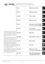
- Directional Control: Details various models and their specifications.
- Pressure Control: Covers systems operating at different pressure levels.
- Flow Control: Discusses flow management through different valve types.
- Modular Valves: Provides information on modular configurations.
- Cartridge Valves: Includes ISO 7368 standards and additional references.
- In-Line Valves: Describes in-line configurations and their applications.
- Subplates: Details subplate options and specifications.
- Proportional Control: Discusses proportional valve control systems.
- Electronics: Covers electronic components and systems integration.
- Systems: Provides an overview of complete system solutions.
- Stackable Valves: Discusses stackable configurations and their benefits.
- DC/AC Standard Coils: Information on UL recognized coils.
- Viscosity: Recommended oil viscosity is 46 mm²/s, with a range of 10 mm²/s to 500 mm²/s.
- Hydraulic Fluid: Use only mineral oil (HL, HLP) as per DIN 51524 to avoid damage.
- Contamination: Oil contamination is a primary cause of faults. Maintain fluid contamination within specified limits according to ISO 4406:1999.
- Working Temperatures: Ambient temperature range is -25°C to +60°C, and fluid temperature range is -25°C to +75°C.
- Seals: Standard O-rings are made of NBR, suitable for specified temperature ranges. For temperatures above 75°C, FKM seals are recommended.
Includes conversion tables for units of force, length, torque, power, pressure, flow rate, and temperature. The document also provides a contamination level table and solenoid valve coil specifications.
The document outlines the specifications for directional control valves, focusing on CETOP standards (NG04, NG06, NG10) and ATEX 2014/34/UE directive compliance. It specifies the surface quality requirements for mounting surfaces, such as roughness (Ra 1.6μm) and flatness (0.03 mm over 100 mm length). The document also details the necessary conditions for fixing screws, electrical wiring, and O-Ring placements to ensure proper installation and operation.
Installation must be performed by qualified personnel. Before removing a coil, disconnect the voltage. Ensure O-Rings are correctly placed to prevent water ingress. Follow the functional limits as indicated in the technical catalogue. Regular checks for cleanliness, wear, and performance are recommended, with oil replacement after the first 100 working hours and subsequently every 2000 hours or annually.
Valves should be handled carefully to avoid impact damage. For storage, keep valves in a dry, dust-free environment, and use preserving oils if stored for over six months. Maintenance includes checking for cleanliness, wear, and performance, and replacing damaged O-Rings with manufacturer-supplied ones.
Valves must be stored in a dry place, protected from dust and corrosive substances. For long-term storage, fill the valve with preserving oils and seal it.
Warranty and supply conditions are detailed in the specific sales contract or the "General terms and conditions of sale" document, available on the manufacturer's website.
The document provides detailed information on various types of directional control valves, including CETOP 2/NG04, CETOP 3/NG06, and CETOP 5/NG10. It describes their design, operation, and specifications, such as maximum pressure, flow rates, and solenoid configurations. The valves are designed for use with hydraulic mineral oils and require specific contamination levels and fluid viscosities.
The document includes a list of abbreviations used in the technical specifications, such as AP (High Pressure Connection), BP (Low Pressure Connection), and DP (Differential Pressure). It also provides technical data for solenoid coils, including voltage, power, and resistance specifications.
The document outlines the ordering code for directional valves, specifying options for electrical operators, spool types, mounting, voltage, and variants. It also lists available coil connection variants and special voltage options.
Pressure drop curves for spools during normal usage are provided, with formulas to calculate losses for specific flow rates. The document includes diagrams showing pressure drop curves and limits of use for different spool types and mounting configurations.
Connectors for directional control valves comply with DIN 43650/ISO4400 standards. They offer protection levels of IP65 and IP67, with various cable gland sizes (PG09, PG11) and color options (black, grey). Connectors with pilot lights and rectifiers are available for different voltage ranges (12-230 VAC/VDC).
Connectors support a maximum AC voltage of 250V and DC voltage of 300V, with a nominal current of 10A and a maximum current of 16A. They are designed for cable sections up to 1.5 mm².
The emergency control lever for solenoid valves enhances safety and flexibility, compatible with CETOP 3 and stackable valves. It is suitable for both directional and proportional valves, providing manual control during power outages.
Products must comply with the 2014/34/UE ATEX Directive for use in explosive atmospheres. The directive outlines safety requirements based on risk evaluation, ensuring products do not exceed 80% of the maximum temperature for their category. It applies to appliances, protection systems, and components used in potentially explosive environments.
Explosive atmospheres are classified into areas based on the probability of occurrence. Area 0/20 indicates constant presence, Area 1/21 indicates probable occurrence, and Area 2/22 indicates low probability. Products are marked with 'G' for gas-air mixtures and 'D' for dust-air mixtures.
Appliances for underground mining and surface plants are categorized based on whether power supply interruption is required in explosive atmospheres. Category M1 offers very high protection levels.
The document provides technical specifications and safety guidelines for AD3XD and AD3XG series solenoid valves, designed for use in explosive atmospheres. These valves comply with the ATEX 2014/34/UE Directive and are suitable for environments where explosive gas, vapor, mist, or dust may be present.
- Group and Category: Group II appliances for non-mining environments, Category 2 for high protection level, and Group I, Category M2 for mining environments.
- Pressure and Flow: Maximum pressure for lines P/A/B is 320 bar, and for line T is 250 bar. Maximum flow rate is 60 l/min.
- Temperature and Fluids: Operates with mineral oils (DIN 51524) at fluid temperatures between -20°C and +40°C, and ambient temperatures within the same range.
- Protection and Certification: IP67 protection degree, with solenoids certified separately under the ATEX Directive.
The valves are part of the "NG06 direction control" range, designed for plate-mounting with compliance to UNI ISO 4401 standards. They are electrically activated, with springs ensuring the spool returns to the center or end position after command cessation.
- Valves must be installed and maintained according to safety regulations for explosive environments, such as CEI EN 60079-14 and CEI EN 61241-14.
- All valves undergo 100% functional testing and are marked with AD3X/ATEX/10 to ensure compliance with technical specifications.
- Safety instructions emphasize the need for qualified personnel for installation and maintenance, and regular inspections for wear and efficiency.
The document includes detailed ordering codes and technical specifications for different variants, including spool types and assembly options. Voltage options for AC and DC are specified, with standard and special configurations available.
Pressure drop curves are provided for normal usage, with calculations for losses at different flow rates. Tests are conducted with mineral oil at a viscosity of 46 mm2/s at 40°C.
The AD3XD and AD3XG series solenoid valves are robust solutions for controlling fluid flow in potentially explosive environments, offering high protection levels and compliance with stringent safety standards.
The document provides technical specifications and guidelines for the AD3XG series directional control valves, compliant with the ATEX Directive 2014/34/UE and IECEx standards. These valves are designed for use in potentially explosive environments and are equipped with explosion-proof coils.
- T4: Maximum surface temperature < 135°C
- T6: Maximum surface temperature < 85°C
- Spool types: 01, 02, 03, 04, 16 (refer to Table 3 for details).
- Assembly types: C, E, F, G, H (refer to Table 1 for details).
- For detailed hydraulic diagrams and assembly instructions, contact Customer Service.
- AC Voltage options: 24V, 48V, 110V, 220V, 230V (50Hz/60Hz)
- DC Voltage options: 12V, 24V, 48V, 110V, 36V, 60V, 125V
- 00: None
- V1: Viton
- LE: Emergency lever
- Dynamic pressure allowed on P for 800,000 cycles.
- Pressure dynamic allowed for 1 million cycles.
- Minimum fluid temperature certified up to -30°C.
- Coil marking for protection class according to ATEX and IECEx standards.
- Follow the instruction handbook carefully before installation.
- Ensure compliance with plant engineering and maintenance regulations for explosive environments.
- Valves must be earthed using anti-loosening and anti-rotation connections.
- Regular inspections for scale, dirt, wear, and efficiency are required.
- Installation and maintenance must be performed by qualified personnel.
The document includes diagrams showing pressure drop curves for spools during normal usage. Tests were conducted with mineral oil at a viscosity of 46 mm²/s at 40°C. The formula for calculating pressure losses at different flow rates is provided.
Details on overall dimensions and installation instructions are provided, including specifications for fixing screws and tightening torque.
The AD3XG series valves are designed for high safety and efficiency in explosive environments, with various configurations and options available to meet specific application needs.
- Designed for high-performance applications with a CETOP 5 interface.
- Features separate solenoid chamber drainage, allowing operation with up to 320 bar back pressure.
- Specifications include a duty cycle of 100% ED, max static pressure of 210 bar, and ambient temperature range of -54°C to 60°C.
- Voltage options range from 12V to 205V, with specific resistance values provided for each.
- NG10 valves designed for subplate mounting, compliant with UNI ISO 4401 standards.
- Equipped with an inductive sensor for safety monitoring, capable of handling max operating pressures of 350 bar at ports P/A/B and 250 bar at port T.
- Max flow rate is 120 l/min, with a fluid viscosity range of 10 to 500 mm²/s.
- These valves automatically reverse actuator movement when flow stops, suitable for systems without electrical devices.
- AD3I and AD3RI are CETOP 3 valves, while AD5I and AD5RI are CETOP 5 valves, each with specific pressure and flow specifications.
- Pressure settings and calibration details are provided, emphasizing the need for precise adjustments to ensure proper operation.
- Used for controlling fluid flow direction, starting, and stopping, featuring a main stage and a CETOP 2 pilot valve.
- Options for internal and external piloting and draining are available, with specific orifice sizes for different lines.
- Ensure compliance with pressure and flow specifications to maintain valve performance and safety.
- Proper installation and maintenance are critical, including adherence to contamination level standards and correct tightening torques for fixing screws.
- Special attention to voltage and resistance specifications is necessary for electrical components.
- ADPH5 Valves: Max operating pressure for ports P/A/B is 250 bar, and for port T (dynamic) is 70 bar. The max flow rate is 120 l/min, with a fluid viscosity range of 10 to 500 mm²/s. The fluid temperature range is -20°C to 75°C.
- ADH5 Valves: Max operating pressure for ports P/A/B is 320 bar, and for port T (int. drainage) is 160 bar. The max flow rate is 100 l/min. The fluid viscosity and temperature ranges are similar to ADPH5.
- ADH7 Valves: Max operating pressure for ports P/A/B is 350 bar, and for port T (ext. drainage) is 250 bar. The max flow rate is 300 l/min, with a fluid viscosity range of 2.8 to 380 mm²/s.
- Switching times for energizing and de-energizing are provided, with variations based on pressure and flow conditions.
- Minimum piloting pressures are specified, with additional requirements for valves with internal drains.
- Check valves are recommended for certain configurations to ensure proper operation.
- Flow Diversion Valves (BDL066): Max pressure 250 bar, max flow 50 l/min, suitable for mineral oils with viscosity 10-500 mm²/s, temperature range -25°C to 75°C.
- Stackable Circuit Selector Valves (CDL106): Max pressure 250 bar, max flow 80 l/min, similar fluid and temperature specifications as BDL066.
- Pressure Control Valves (PV*3 / PV*U3): Max pressure 320 bar, setting ranges up to 250 bar, max flow 40 l/min.
- Coils are available in various DC voltages: 12V, 24V, 28V, 48V, 110V, and special voltages.
- Coils with Hirschmann and AMP Junior connections are supplied without connectors, which can be ordered separately.
- Fixing screws and tightening torques are specified for different valve types.
- Valves are designed for easy integration into hydraulic systems with minimal pressure drop.
- Valves allow simultaneous connection of multiple systems, simplifying hydraulic layouts.
- High-performance solenoids eliminate the need for external drainage.
- Special voltages and variants are available upon request.
- Compliance with European low voltage directive is required for certain components.
1. Maximum operating pressure: 320 bar
2. Nominal regulated flow rate: 1 to 24 l/min
3. Hydraulic fluids: Mineral oils DIN 51524
4. Fluid temperature range: -25°C to 75°C
5. Ambient temperature range: -25°C to 60°C
6. Fluid viscosity: 10 to 500 mm²/s
7. Maximum contamination level: Class 10 according to NAS 1638 with filter ß25 75
8. Weight: 1.5 Kg
9. Fixing screws: UNI 5931 M5x40, material specification min. 12.9, tightening torque 6.5 to 7 Nm
Flow Rate Ranges:
1. Q1 = 1.5 l/min
2. Q2 = 3 l/min
3. Q3 = 9 l/min
4. Q4 = 19 l/min
5. Q5 = 24 l/min
Modular Valves:
1. CETOP 2, 3, 5, 7
2. Types include direct check valves, pilot operated check valves, maximum pressure valves, flow regulators, back pressure valves, and pressure reducing/sequencing valves.
Abbreviations:
1. AP: High pressure connection
2. BP: Low pressure connection
3. DP: Differential pressure (bar)
4. Q: Flow (l/min)
5. PR: Reduced pressure (bar)
Key Features of Specific Valves:
- AM2UD Modular Direct Check Valves: Max pressure 250 bar, flow 20 l/min, available with 1 or 5 bar springs.
- AM2UP Modular Pilot Operated Check Valves: Max pressure 250 bar, flow 20 l/min, piloting ratio 1:4.
- AM2VM Modular Maximum Pressure Valves: Max pressure 250 bar, flow 20 l/min, setting ranges from 30 to 250 bar.
- AM2QF Modular Flow Regulator: Max pressure 250 bar, flow 20 l/min, regulation on 6 screw turns.
- AM3UD Modular Direct Check Valves: Max pressure 350 bar, flow 40 l/min, available with 1 or 5 bar springs.
- AM3UP Modular Pilot Operated Check Valves: Max pressure 350 bar, flow 40 l/min, piloting ratios 1:4 and 1:12.5.
- AM3VM Modular Maximum Pressure Valves: Max pressure 320 bar, flow 40 l/min, setting ranges from 50 to 320 bar.
- AM3CP Modular Back Pressure Valve: Max pressure 350 bar, flow 40 l/min, setting ranges from 50 to 320 bar.
- AM3RD/AM3SD Modular Pressure Reducing/Sequencing Valves: Max pressure 350 bar, flow 40 l/min, setting ranges from 2 to 250 bar.
- AM3VR: Pilot-operated pressure reducing valves with relieving features, allowing excess flow to be diverted to a reservoir.
- AM3VS: Sequencing valves ensure secondary circuit pressurization upon reaching set pressure.
- AM3SH: Shuttle valves select the highest pressure signal for external port signaling.
- AM3QF: Non-compensated throttle valves for flow regulation, adjustable via grub screw or plastic knob.
- AM66: Compensated flow control assemblies for two-speed operation in hydraulic systems.
- AM3RGT: Valves for regenerative circuits to increase actuator speed.
- AM5UD: Direct check valves allowing free flow in one direction, with conical seated poppet preventing reverse flow.
- Hydraulic Fluids: Mineral oils DIN 51524
- Fluid Viscosity: 10 ÷ 500 mm²/s
- Fluid Temperature: -25°C ÷ 75°C
- Ambient Temperature: -25°C ÷ 60°C
- Max. Contamination Level: Class 10 in accordance with NAS 1638 with filter ß25 75
- Max. Operating Pressure: 280 bar
- Max. Flow: 80 l/min
- Features: Allows free flow in one direction and piloted return in the opposite direction.
- Max. Operating Pressure: 350 bar
- Setting Ranges: 50, 140, 350 bar
- Adjustment: Grub screw or plastic knob
- Max. Operating Pressure: 350 bar
- Setting Ranges: 30, 140, 250 bar
- Features: Direct acting with bypass non-return valves.
- Max. Operating Pressure: 350 bar
- Setting Ranges: 60, 120, 250 bar
- Features: Includes a relieving system to manage pressure variations.
- Max. Operating Pressure: 350 bar
- Setting Ranges: 60, 120, 250 bar
- Features: Ensures secondary circuit pressurization.
- Max. Operating Pressure: 350 bar
- Max. Flow: 80 l/min
- Features: Selects highest pressure signal for actuator load.
- Max. Operating Pressure: 350 bar
- Max. Flow: 100 l/min
- Features: Non-compensated throttle valve with adjustable flow rate.
- Max. Operating Pressure: 320 bar
- Features: Intermediate block for modular mounting of flow rate regulators.
- All valves are compatible with CETOP 5/NG10 standards.
- Adjustment options include plastic knob or grub screw.
- Valves are available with Viton seals as an option.
- Max operating pressure: 320-350 bar depending on the valve type.
- Hydraulic fluids: Mineral oils DIN 51524.
- Fluid viscosity: 10 ÷ 500 mm²/s.
- Fluid temperature: -25°C to 75°C.
- Ambient temperature: -25°C to 60°C.
- Contamination level: Class 10 according to NAS 1638 with filter ß25 75.
- These valves allow for two-speed operation in hydraulic systems via electrical changeover commands.
- They require a separate flow rate regulator (QC32) for optimal performance.
- Solenoids used are standard type A16 for DC voltage.
- Various configurations are available based on size, electrical operation, and control lines.
- Voltage options include 12V, 24V, 48V, 110V, 102V, and 205V.
- Variants include options for Viton seals and special voltage requirements.
- Designed to increase actuator speed in hydraulic systems.
- Max flow at ports A/B/P/T is 70 l/min.
- Weight is approximately 2.1 Kg.
- Allow free flow in one direction and controlled return flow in the opposite direction.
- Max flow is 250 l/min with a piloting ratio of 1:11.7.
- Weight is approximately 7.2 Kg.
- Non-compensated throttle valves with flow rate regulation over 10 screw turns.
- Available in configurations for single or double line control.
- Weight varies slightly based on configuration.
- Composed of a cover and an operating unit, these valves are used for direct control, non-return, pressure control, and flow rate regulation.
- Max nominal flow rate is 150 l/min for NG16 and 350 l/min for NG25.
- Designed for minimal thermal dissipation and reduced hydraulic plant weight.
- Maximum Pressure: Cartridge valves can control pressures up to 400 bar and a maximum flow rate of 350 l/min for NG25.
- Nominal Sizes: Available in NG16 and NG25.
- Setting Ranges: 15 to 400 bar, with different springs for specific ranges.
- KEC16/25RI: Cover with external piloting port, allowing flow regulation in both directions.
- KEC16/25CQ: Cover with stroke limitation for flow control.
- KEC16/25PC: Cover with hydraulic release pilot valve, suitable for solenoid pilot valve mounting.
- KEC16/25RC: Cover with interface NG6.
- KEC16/25SH and SP: Covers with integral changeover valve and interface NG6.
- Each cover type has specific weight, fixing screws, and tightening torque requirements.
- Standard orifices are calibrated to 1 mm diameter.
- Manual Pressure Regulation: Incorporated in the cartridge closing cover with remote piloting options.
- Electrical Command: Options for discharge to drain and proportional pressure control.
- Two-Level Pressure Unit: Allows for manually adjustable and electrically selected pressure levels.
- KRA Series: Includes electrical position control for safety applications, such as hydraulic presses.
- Proximity Sensors: Inductive sensors detect metal objects to ensure safety and operational efficiency.
- Outlet: PNP-NA
- Wiring: 1 = brown (positive), 3 = blue (negative), 4 = black (positive signal)
- Max. pressure: 500 bar
- External diameter: M12x1
- Release distance: 0 ÷ 1.1 mm
- Stabilized supply: 10 ÷ 30 VDC
- Release hysteresis: 0.2 mm
- Max. current supplied: 130 mA
- Residual undulation: 15%
- Max switching frequency: 1000 Hz
- Casing material: stainless steel
- Degree of protection: IP68 on active surface
- Ambient temperature: -25°C to 70°C
- Short circuit protection: Yes
- TUA: Reamed working length
- Overall dimensions connector: IP67
- Ambient temperature: -40°C to 85°C
- Ordering code: V86400003
- High pressure connection: AP
- Low pressure connection: BP
- Stroke: C (mm)
- Differential pressure: DP (bar)
- Flow: Q (L/min)
- Pump flow: QP (L/min)
- Various subplate models and configurations are listed with specific dimensions, weights, and connection types.
- Various modular components are described with specifications for pressure settings, connection types, and assembly instructions.
- Components include base plates, intermediate modules, and dowel carrier plates for solenoid valves.
- A comprehensive list of abbreviations used in the document is provided, detailing connections, pressure settings, and component types.
The document provides detailed specifications for various hydraulic components, including connectors, subplates, and modular components. It includes information on dimensions, weight, and material composition, such as cast iron and aluminum. The components are designed for use with CETOP 3/NG6 and CETOP 5/NG10 standards.
Instructions for assembling and installing the components are provided, including the use of specific fixing screws and tightening torques. The document emphasizes the importance of adhering to specified pressure settings and using appropriate springs for different pressure ranges.
The components conform to CETOP standards, ensuring compatibility and interchangeability within hydraulic systems. The document also references DIN 51524 for hydraulic fluids and NAS 1638 for contamination levels.
Recommendations include using mineral-based oils with specific viscosity ranges and maintaining fluid and ambient temperatures within specified limits. The document advises on the use of pressure relief valves to enhance safety and prevent pressure peaks.
The document includes tables listing various components with their dimensions, weight, and configurations. Charts illustrate pressure-flow relationships and setting pressures for different spring types. The maximum operating pressure for certain valves is 320 bar, with flow rates up to 40 l/min.
Critical parameters include the maximum permissible setting pressures, tightening torques, and the use of specific springs for different pressure ranges. The document highlights the importance of using the correct components and configurations to ensure system safety and efficiency.
1. Specifications:
- The document details various pressure compensation valves, specifically CETOP 3/NG6 and CETOP 5/NG10 models.
- Flow rates for CETOP 3/NG6 range from 5 to 28 l/min, while CETOP 5/NG10 ranges from 45 to 105 l/min.
- Pressure settings are categorized into ranges: 8-50 bar, 25-170 bar, and 50-315 bar.
- Voltage options include 9VDC, 12VDC, and 24VDC with varying current requirements.
2. Features and Variants:
- Valves can be equipped with or without a manual pressure limiter and rotary emergency features.
- Variants include options like Viton seals and rotary emergency levers.
- Connectors are not included and must be ordered separately.
3. Operating Conditions:
- The valves operate optimally with mineral-based oil at a viscosity of 46 mm2/s at 40°C.
- Maximum operating pressures are specified for different ports, with dynamic pressure allowances for up to 2 million cycles.
- Fluid temperature range is -20°C to 75°C, with a contamination level class 8 as per NAS 1638.
4. Electronic Control Units:
- The document specifies the use of REMSRA electronic control units for single solenoid control.
- Recommended dither frequency is 100 Hz for optimal performance.
5. Installation and Maintenance:
- Detailed instructions for installation, including fixing screws and torque specifications, are provided.
- The document emphasizes the importance of using specified electronic control units and maintaining fluid conditions for optimal valve performance.
6. Diagrams and Symbols:
- Various diagrams illustrate flow rates, pressure settings, and valve configurations.
- Hydraulic symbols are provided for different valve versions, including 2-way and 3-way pressure compensated models.
7. Ordering Information:
- The document includes detailed ordering codes for different valve configurations and variants.
- It highlights the need to specify connectors and additional components separately.
- Designed for single solenoid proportional valves, compliant with EN 175301-803 standards.
- Features pulse width modulation (PWM) with current feedback for proportional solenoid output.
- Adjustments available for gain, minimum current, and ramp times via potentiometers.
- Electrical specifications include power supply requirements (12VDC or 24VDC), peak supply (40VDC), and protection type (IP65).
- Complies with ROHS 2011/65/UE Directive and European norms for electromagnetic compatibility.
- Designed for single solenoid proportional valves without integral position transducers.
- Enclosed in an OCTAL type housing, operates on PWM principle with current feedback.
- Features overload protection, ramp time adjustments, and serial interface for parameter adjustments.
- Electrical specifications include power supply (10VDC to 30VDC), maximum supply voltage (36V), and current output settings.
- Complies with ROHS 2011/65/UE Directive and European norms for electromagnetic compatibility.
- Designed for double solenoid proportional valves without integral position transducers.
- Enclosed in an UNDECAL type housing, operates on PWM principle with current feedback.
- Features overload protection, ramp time adjustments, and serial interface for parameter adjustments.
- Electrical specifications include power supply (10VDC to 30VDC), maximum supply voltage (36V), and current output settings.
- Complies with ROHS 2011/65/UE Directive and European norms for electromagnetic compatibility.
- Detailed procedures for calibration, including minimum and maximum current adjustments, ramp time settings, and connection diagrams.
- Recommendations for typical connections and settings for various proportional valves.
- Emphasizes the importance of protecting electronic regulators from dampness and water.
- Power Supply: 10 ÷ 30 VDC, with a maximum supply voltage of 36 V.
- Power Absorption: 40 W.
- Current Output: Configurable via dip switches with maximum settings of 2.8A, 1.76A, and 0.88A.
- Signal Input: Differential input (–5V ÷ +5V) or positive voltage (0V ÷ +5V).
- Ambient Operating Temperature: -20 ÷ +70°C.
- Ensure proper connection without powering the card initially.
- Adjust trimming potentiometers for minimum current and ramp time.
- Power the card and adjust the reference signal for minimum current detection.
- Set gain and ramp time for desired actuator speed and response.
- Two types of command signals: differential and positive voltage.
- External potentiometer or resistor required for certain configurations.
- Direct connection between REM and solenoid is mandatory.
- Shared connections with other electrical equipment are not recommended.
- DG software for digital adjustment of REMS and REMD boards.
- Self-leveling device LAB3 for aerial platforms with safety features and PWM output.
- Proper adjustment of ramp times is crucial to prevent unintended actuator movements.
- Overload conditions require power cycling after resolving the cause.
- MAV1152: Designed for controlling one proportional solenoid and additional switching valves. It supports up to 5 analog inputs and 1 PWM current output, with a maximum load of 9 Amperes. It includes RS232 interface for diagnostics and parameter settings.
- MAV1152HY: Similar to MAV1152 but optimized for joystick control. It features 1 PWM output and 5x2 switched outputs, with optional CANbus communication. Default settings include a PWM frequency of 150 Hz and a maximum current output of 1700mA.
- MAV4211: Controls proportional solenoids and additional switching functions, supporting up to 4 analog inputs and 8 PWM outputs. It is compatible with joysticks outputting a 10-90% signal.
This document provides technical specifications and operational guidelines for various joystick models and hydraulic systems. It includes details on electrical and mechanical features, connector configurations, and ordering codes for different joystick types and pressure units.
- JC Heavy Duty Single Joystick: Available in single (Y) or dual (XY) axis configurations, with options for operator present trigger switches. Electrical features include potentiometer resistance of 1.4 to 2.2 K, max supply voltage of 32V DC, and max output current of 5 mA. Mechanical features include a mechanical angle of ±20°, max operating load of 390 N, and mechanical life of 7,500,000 cycles. Ambient operating temperature ranges from -40°C to +80°C, with IP65 protection.
- JCFD Single-Axis Fingertip Joystick: Designed for precise fingertip control with a compact, low-profile design. Electrical features include potentiometer resistance of 5 K, max supply voltage of 32V DC, and max output current of 2 mA. Mechanical features include a mechanical angle of ±30°, max operating load of 50 N, and mechanical life of 5,000,000 cycles. Ambient operating temperature ranges from -25°C to +70°C, with IP66 protection.
- Low/High Pressure Units: These units are used in hydraulic systems with dual pumps forming a single pressure circuit. They feature adjustable maximum pressure valves for system protection. The document provides ordering codes for various configurations, including subplate mounting and modular component connections.
The document details the pin allocation for joystick connectors, including 12-way handle connections and 16-way primary potentiometer connections. It also includes information on spare parts and connector types.
The products comply with European norms for electromagnetic immunity (IEC 61000-4-3) and emissions (EN6550022), and are in accordance with the ROHS 2011/65/UE Europe Directive.
Catalog excerpts
© 2018 Dana Brevini S.p.A. All rights reserved. Hydr-App, SAM Hydraulik, Aron, Brevini Hydraulics, BPE Electronics, VPS Brevini, OT Oiltechno-logy, logos are trademarks or are registered trademarks of Dana Brevini S.p.A. or other companies of the Dana Group in Italy and other countries. The technical features supplied in this catalogue are non binding and no legal action can be taken against such material. Dana Brevini will not be held responsible for information and specifications which may lead to error or incorrect interpretations. Given the continuous technical research aimed at improved...
Open the catalog to page 3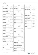
STUDS - MODULAR VALVES
Open the catalog to page 6
OIL VISCOSITY ACCORDING TO TEMPERATURE Read this instructions carefully before installation. All operations must be carried out by qualified personnel following the instructions. The user must periodically inspect, based on the conditions of use and the substances used, the presence of corrosion, dirt, the state of wear and correct function of the valves. Always observe first the operating conditions given in datasheet of the valve. Observe the recommendations given in the data sheet of the valve. Use only mineral oil (HL, HLP) according to DIN 51524. Use of other different fluids may damage...
Open the catalog to page 7
Table 2: Reccomanded contamination level. BREVINI Motion Systems
Open the catalog to page 8
Directional control valves High pressure connection Phase lag (degrees) Low pressure connection Stroke(mm) Across flats Internal across flats Amplitude decay (dB) Differential pressure (bar) Force (N) Input current (A) Manometer connection Knob turns Seal ring Load pressure (bar) Parbak ring Parallel connection Reduced pressure (bar) Flow (l/min) Pump flow (l/min) Elastic pin Ball Series connection Piloting Drainage DIRECTIONAL CONTROL VALVES CETOP 2/NG04 ATEX 2014/34/UE directive CETOP 5/NG10 CETOP 5/NG10 High performances Automatic reciprocating valves Piloted valves and subplate mounting Flow...
Open the catalog to page 9
BREVINI Motion Systems
Open the catalog to page 10
AUTOMATIC RECIPROCATING VALVES PILOTED VALVES AND SUBPLATE MOUNTING CETOP 5/NG10 HIGH PERFORMANCES CETOP 3/NG06 FLOW DIVERSION VALVES CETOP 3 OTHER OPERATORS STANDARD CONNECTORS
Open the catalog to page 11
Standard connectors Cap. I • 20 Directional control valves CETOP 2/NG4 The directional control valves NG4 are designed for subplate mounting with an interface in accordance with UNI ISO 4401 - 02 - 01 - 0 - 94 standard (ex CETOP R 35 H 4.2-4-02), and are the smallest on the market in their category whilst still featuring excellent performance. The use of solenoids with wet armatures ensures quiet operation, means that dynamic seals are no longer required and important levels of counter-pressure are accepted on the return line. The solenoid's tube is screwed at valve body directly, while a...
Open the catalog to page 12
Variant Code No variant (without connectors) S1(*) Viton SV(*) Emergency button ES(*) Rotary emergency button P2(*)(**) AMP Junior connection AJ(*) Solenoid with flying leads (250 mm) FL Solenoid with flying leads (130 mm) integrated diode LD Deutsch connection with bidir. diode CX Specials (with price increasing) Other variants available on request. (*) Coils with Hirschmann and AMP Junior connection supplied without connectors. The connectors can be ordered separately, Cap. I • 20. (**) P2 Emergency tightening torque max. 6*9 Nm / 0.6 * 0.9 Kgm with CH n. 22 Voltage...
Open the catalog to page 13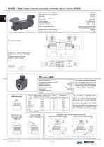
Max. pressure ports P/A/B Max pressure port T (dynamic) Max flow Max excitation frequency Duty cycle Fluid viscosity Fluid temperature Ambient temperature Max contamination level Weight with one DC solenoid Weight with two DC solenoids DC coils A09 Type of protection (in relation to connector used) IP 65 Insulation class wire H • The AMP Junior coil, the Deutsch coil with bidirectional diode and the coil with flying leads (with or without diode) coils are available in 12V or 24V DC voltage only. The european low voltage directive is applied to electronical equipments used at a nominal voltages...
Open the catalog to page 14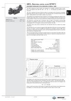
Standard connectors Cap. I • 20 ADC3... Directional control valves CETOP 3 solenoid operated with reduced overall size The NG6 directional control valves are designed for subplate mounting with an interface in accordance with UNI ISO 4401 - 03 - 02 - 0 - 94 standard (ex CETOP R 35 H 4.2-4-03). The use of solenoids with wet armatures allows an extremely safe construction completely dispensing with the need for dynamic seal. The solenoid tube is screwed directly onto the valve casting whilst the coil is kept in position by a ring nut. The operation of the directional valve is electrical. The...
Open the catalog to page 15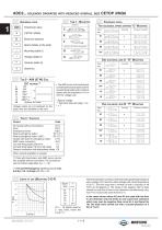
Ordering code Directional valve CETOP 3/NG6 Electrical operator Spool (tables at the side) Mounting (table 1) Voltage (table 2) Variants (table 3) Serial No. • The AMP Junior coil, the Deutsch coil with bidirectional diode and the coil with flying leads (with or without diode) coils are available in 12V or 24V Dc voltage only. * Special voltage ** Technical data see page Cap. I • 7 Voltage codes are not stamped on the plate, their are readable on the coils. No variant (without connectors) S1(*) Viton SV(*) Emergency button ES(*) Rotary emergency button P2 (*)(**) Rotary emergency...
Open the catalog to page 16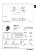
ADC3... solenoid operated with reduced overall size CETOP 3/NG6 A09 DC coils Type of protection (in relation to connector used) IP 65 Insulation class wire H • The AMP Junior coil, the Deutsch coil with bidirectional diode and the coil with flying leads (with or without diode) coils are available in 12V or 24V DC voltage only. The european low voltage directive is applied to electronical equipments used at a nominal voltages between 50 and 1000 VAC or 75 and 1500 VDC. In conformity with the low directive each part of the manifold or the subplate on which the valve is mounted should be connected...
Open the catalog to page 17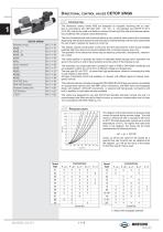
Directional control valves CETOP 3/NG6 CETOP 3/NG06 Standard spools AD3E... AD3E...J* AD3E...KJ AD3V... AD3L... Other operator AD3P... AD30... AD3M... AD3D... “D15” DC Coils “B14” AC Solenoids Standard connectors “LE” Variants l.v.d.t. Introduction The directional control valves NG6 are designed for subplate mounting with an interface in accordance with UNI ISO 4401 - 03 - 02 - 0 - 94 standard (ex CETOP R 35 H 4.2-4-03), and can be used in all fields on account of their high flow rate and pressure capacities combined with compact overall dimensions. The use of solenoids with wet armatures allows...
Open the catalog to page 18All Brevini Power Transmission catalogs and technical brochures
 S series
164 Pages
 Slewing drives
112 Pages
 BGM
BGM18 Pages
 S6CV
S6CV64 Pages
 MEDIUM PRESSURE MOTORS AND PUMPS
124 Pages
 series 498
2 Pages
 series 492
2 Pages
 series 392/393
2 Pages
 SH11C
SH11C24 Pages
 H1C
H1C18 Pages
 INDUSTRIAL SERIES
260 Pages
 LEONESSA BREVINI
57 Pages
 Hand pumps
40 Pages
 VPS Mobile Valves
68 Pages
 MC Tubes kit / Kit tub
38 Pages
 MC Hydraulic power pack
64 Pages
 FP Hydraulic power pack
100 Pages
 MB Orbital geared motors
20 Pages
 Low speed high torque Orbital Motors
192 Pages
 Axial piston Pumps and Motors
530 Pages
 Rotary Drilling
5 Pages
 Bulk Mining Industrail
11 Pages
 Deck Crane Brochure
5 Pages
 Off-highway Product Range
13 Pages
 Hoisting and Recovery Winches
125 Pages
 MOBILE SLEWING DRIVES
106 Pages
 SU IM SERIES
40 Pages
 ML B RD SERIES
48 Pages
 MR
MR4 Pages
 MP
MP1 Page
 MC
MC38 Pages
 MB
MB20 Pages
 BFP
BFP4 Pages
 M series
408 Pages
 K series
488 Pages
 V series
224 Pages
 Hoisting&Recovery Winches
115 Pages
 WINCH DRIVES
16 Pages
 INDUSTRIAL PLANETARY GEARBOXES
260 Pages
 ASu Series
3 Pages
 ASu66 Series
3 Pages
 SP MkII Series
2 Pages
 TAC MkII Series
2 Pages
 TLu Series
2 Pages
 TLu66 series
2 Pages
 VT Series
8 Pages
 MC4 Series
8 Pages
 MC2 Series
8 Pages
 Powerpacks
4 Pages
 FP Series
80 Pages
 Take Up Winches for mining
16 Pages
 S Series Big
20 Pages
 Marine Technologies
14 Pages
 Winches overview
16 Pages
 Sugar mill drives
22 Pages
 Hydraulic Cylinders
2 Pages
 OT Silent Plus Pumps
10 Pages
 OT 300 Group 3 pumps
68 Pages
 OT 200 Group 2 pumps
127 Pages
 OT 100 Group 1 pumps
84 Pages
 S6CV Pumps
68 Pages
 SH11C Pumps
20 Pages
 SH5AV Pumps
28 Pages
 MD10V Pumps
99 Pages
 BRZ Orbital Motors
10 Pages
 HT Orbital Motors
19 Pages
 HR Orbital Motors
27 Pages
 AR - ARS Orbital Motors
22 Pages
 BR-BS Orbital Motors
30 Pages
 BGM Orbital Motors
19 Pages
 BG-BH Orbital Motors
31 Pages
 SH7VR Series
49 Pages
 SH7V Series
74 Pages
 MD11V Series
13 Pages
 SH11CR Series
16 Pages
 SH11C Series
24 Pages
 Twin Screw Extruder Drives
12 Pages
 Planetary Bevel Helical Posiplan
125 Pages
 S-Series Planetary Gearboxes
162 Pages
 Industrial Planetary Gearboxes
260 Pages
 Yaw and Pitch Drives
106 Pages
 Planetary wheel drives
129 Pages
 Helical & Bevel helical Gearboxes
171 Pages
 Lifting / Hoisting Gearboxes
37 Pages
 Long Travel Drives
12 Pages
 Conveyor Drives
12 Pages
 Single Screw Extruder Drives
115 Pages
 Injection Molding Drives
12 Pages
 Recovery winches
115 Pages
 Winch drives
108 Pages
 Atex Gearboxes Catalogue
30 Pages
 Slewing drives
110 Pages
 S-Series
160 Pages
 Catalog
250 Pages



Archived catalogs
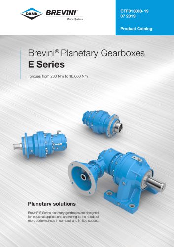 E series_2019
272 Pages
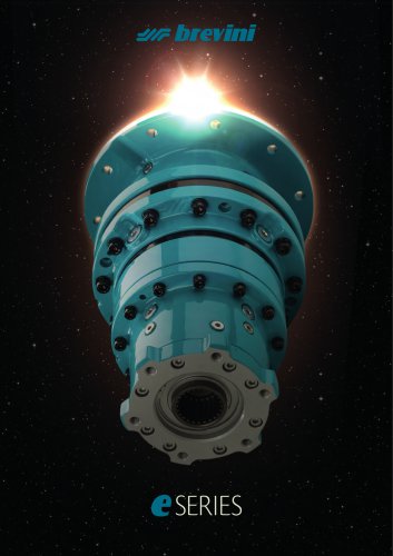 E Series
5 Pages
 CATALOGUE E series
274 Pages
- Electric gearmotor
- Planetary gearbox
- Coaxial gearhead
- Right angle gearhead
- Compact gearhead
- Solid-shaft gearhead
- Hollow-shaft gearhead
- Winch
- Gear train gear reducer
- Gearbox for industrial applications
- Transmission gearhead
- Multi-stage gearhead
- Single-stage gearhead
- AC gear-motor
- Right angle electric gearmotor
- Coaxial gearmotor
- Shaft gearhead
- Helical gear gearhead
- Solid-shaft gear-motor
- Gear train gearmotor