
- Catalogs
- Brevini Power Transmission
- S6CV Pumps


- Products
- Catalogs
- News & Trends
- Exhibitions
S6CV Pumps

S6CV Pumps
The S6CV series consists of variable displacement axial piston pumps designed for closed circuit hydrostatic transmissions. These pumps utilize a swash plate design, capable of operating at pressures up to 400 bar. The flow rate is determined by the rotation speed and swash plate angle, allowing for flow direction inversion by adjusting the plate angle.
The series includes various control options such as manual, hydraulic, and electric controls, with feedback and non-feedback mechanisms. Specific models include HLR, HLS, HIR, HIN, HER, HEN, HE2, HEH, and automotive options.
- Fluids: Use mineral oil-based fluids with specific additives, maintaining viscosity between 15-40 cSt at operating temperature.
- Temperature: Operating range is -25 ºC to 90 ºC.
- Filtration: A 10 μm absolute filter is recommended, with a maximum pressure drop of 0.2 bar.
- Pressure: Main pump continuous pressure is 400 bar, peaking at 450 bar. Charge pump nominal pressure is 25 bar, with a maximum of 40 bar.
- Seals: Standard seals are FKM (Viton ®).
Pumps can be installed in any position, with the input shaft capable of handling both radial and axial loads, ensuring a service life of at least 80% compared to unloaded bearings.
Charge pump displacement options range from 18 to 27 cm³/rev. The maximum permissible continuous pressure in the housing is 4 bar, with short-term peaks up to 6 bar.
An alphanumeric code system specifies pump configurations, including displacement, mounting flange, direction of rotation, and control type.
- Pressure Ratings: Various pressure ratings for components like cut-off and pressure relief valves, with standard ratings at 420 bar for certain valves.
- Cut-Off Valves: Options include without cut-off, electric cut-off, and electric cut-off with pressure compensator, not available with HME-HMI control.
- Pressure Relief Valves: Available in different settings, standard at 420 bar for side B and 22 bar for charge pressure.
- Filters: Options include without filter, optical clogging sensor, and electric clogging sensor, not available with HME-HMI control.
- Displacement Limitation: Standard displacement is 75 cm3/rev, with options from 0 to 74 cm3/rev.
- Control Features: Various control options adjust pump displacement based on lever angle or pilot pressure.
- Inching Options: Hydraulic and mechanical inching options with specific voltage and control orifice diameter requirements.
- Safety Note: The spring return feature is not a safety device. Contaminants in hydraulic fluid can cause the spool valve to stick, leading to unsafe conditions.
- Control Orifices: Different diameters affect response times. For specific requirements, contact the sales office.
- Through Drive: Options for through drive assembly for a second pump with various flange configurations.
- Pump Features: Options include a bypass valve and conversion cables for connectors.
- Options: Include black painting (RAL 9005) and other customizations.
- Sensor Features: Inductive principle with PNP output, suitable for a voltage range of 10-34 V and a temperature range of -25°C to +85°C.
- Torque Requirements: Torque necessary at the control lever ranges from 1 to 2.45 Nm.
The document outlines specifications for hydraulic and electric proportional controls used in pumps. Pilot pressure for hydraulic controls ranges from 6 to 18 bar, with a maximum of 30 bar for certain configurations. Electric controls require a current input, with standard solenoids operating at 24V d.c. and optional ones at 12V d.c.
Pump displacement is proportional to pilot pressure or input current, affecting flow direction and displacement. External control units are necessary to manage these inputs effectively.
Tolerance on piloting pressure and current is ±10% of the maximum value. Operating conditions include viscosity, temperature, speed rotation, and working pressure.
Review applications with Brevini Fluid Power to ensure correct setup, especially when using HIN and HEN controls. Additional safety systems may be needed due to the non-safety nature of the spring return feature.
Response times for control commands vary based on orifice dimensions, with detailed tables provided for different configurations. These times are indicative and may vary between production lots.
Potential contamination in hydraulic fluid can cause the spool valve to get stuck, affecting pump performance. Additional safety measures may be needed for specific applications.
The document outlines specifications for a hydraulic pump system, including the direction of rotation and its correlation with flow direction. It details electric proportional control with hydraulic emergency override, emphasizing that ports Y1 and Y2 should not have back pressure during normal operation.
Emergency operation procedures include using a spring return feature that is not a safety device. Contamination in hydraulic fluid could affect the spool valve's position.
Response times for the HEH control vary with orifice sizes from 0.5 mm to 1.5 mm, with times ranging from 7 seconds to 1 second.
Key operating conditions include a viscosity and temperature of 38cSt at 50°C, a speed rotation of 1500 RPM, a working pressure of 250 bar, and a charge pressure of 22 bar.
The "AUTOMOTIVE" control used in hydrostatic transmissions includes vehicle speed control, torque limitation, and the ability to control flow direction electrically and hydraulically. It also mentions the use of a flushing valve for oil cooling.
The pressure compensator valve maintains constant circuit pressure and is recommended for systems with frequent pressure peaks. The electric cut-off valve stops the pump flow when the power supply is cut off, designed for safety applications.
The S6CV pump can be equipped with a pressure filter to maintain optimal fluid contamination levels. The filter uses a composite fiber element with a 12-micron absolute capacity and includes clogging sensors.
The by-pass valve allows connection between pressure ports A and B when necessary, requiring a specific procedure to open.
Detailed dimensions for the pump, controls, and accessories, including various ports and their specifications, are provided.
Availability of through drives for connecting a second pump and types of flanges available for different configurations are mentioned.
The document provides technical specifications and operational guidelines for various types of hydraulic pump controls, including manual lever, hydraulic proportional, and electric proportional controls. It emphasizes the importance of feedback systems and safety considerations.
- Manual Lever Control: Pump displacement is directly proportional to the lever angle. The feedback system automatically corrects swashplate positioning errors. Torque required at the control lever is between 1 and 2.45 Nm.
- Hydraulic Proportional Control: Displacement is proportional to pilot pressure at ports Y1 or Y2, affecting flow direction. Pilot pressure ranges from 6 to 18 bar, with a tolerance of ±10%.
- Electric Proportional Control: Displacement is proportional to the input current of solenoids. Standard solenoids operate at 24V d.c. with a max current of 1A.
- Feedback systems are integral to correcting positioning errors in all control types.
- For hydraulic controls, piloting pressure must be controlled by a joystick or pressure reducing valve.
- Electric controls require an external amplifier card for solenoid current regulation.
- The spring return feature is not a safety device. Contamination can cause the spool valve to stick, preventing the pump from supplying the specified flow.
- Applications may require additional safety measures, such as an emergency stop.
- Response times for controls vary based on orifice size and production lots.
- Sensor: Inductive principle, PNP output, operating voltage 10-34V, temperature range -25°C to +85°C, IP67 protection.
- Operating Conditions: Viscosity 38cSt, temperature 50°C, speed 1500 RPM, working pressure 250 bar.
The document outlines various control systems for pumps, including Electric Proportional Control (HER), Electric On-Off Control (HE2), and Electric Proportional Control with Hydraulic Emergency Override (HEH). It specifies the response times for different orifice dimensions and operating conditions such as viscosity, temperature, speed rotation, working pressure, and charge pressure.
The document describes the operation of solenoids in controlling pump displacement and flow direction. It emphasizes the need for external amplifier cards for controlling solenoid input currents and provides guidelines for emergency operations.
It is recommended to use specific amplifier cards for S6CV and to review motor and vehicle parameters when using HEN control. The document advises consulting Brevini Fluid Power for HEN applications.
Response times are indicative and may vary between production lots. The spring return feature is not a safety device, and contamination can cause the spool valve to stick. Y1 and Y2 ports should not have back pressure during normal operation.
Response times for different orifice sizes range from 7.5 seconds to 1 second, depending on the orifice dimension and direction of flow change.
The document also covers the Automotive control system used in hydrostatic transmissions, which includes speed control, torque limitation, and flow direction control. It mentions the use of a flushing valve for oil cooling.
The pressure compensator valve maintains constant circuit pressure and is recommended for systems with frequent pressure peaks. The electric cut-off valve stops the pump flow when the power supply is cut off, designed for safety applications.
The S6CV can be equipped with a pressure filter to maintain optimal fluid contamination levels. The filter uses a composite fibre element with 12-micron absolute capacity and includes clogging sensors.
The document provides detailed specifications for various hydraulic components, including filters, pumps, and control valves. It highlights the availability of a remote filter version and the compatibility of filters with cut-off valves. The dimensions and configurations of pumps and controls are extensively detailed, including displacement settings and pressure ports.
The document outlines the dimensions for pumps, controls, and shafts, specifying various configurations for tandem pump combinations. It includes detailed measurements for pressure ports, case drains, and suction ports, with specifications for both ISO and SAE standards.
Several types of control valves are described, including starting control, torque control, hydraulic inching, and thermostatic valves. The document specifies the ports for piloting pressure and drainage pressure gauges.
The document details the dimensions and configurations for splined shafts, including ANSI and DIN standards. It also discusses through drive capabilities for the S6CV 128 pump, including available flanges and maximum permissible torques.
Configurations for tandem pump combinations are provided, specifying the necessary through drives for different shaft types. The document includes examples of tandem pump setups and the required configurations for specific shaft types.
The document includes a disclaimer about the non-binding nature of the technical features and the responsibility of Brevini Fluid Power. It emphasizes the importance of adhering to operating limits and assessing application conditions to ensure safety.
General terms and conditions of sale are referenced, directing readers to the Brevini Fluid Power website for more information.
Catalog excerpts
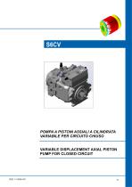
POMPA A PISTONI ASSIALI A CILINDRATA VARIABILE PER CIRCUITO CHIUSO VARIABLE DISPLACEMENT AXIAL PISTON PUMP FOR CLOSED CIRCUIT
Open the catalog to page 1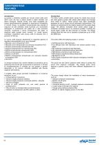
CARATTERISTICHE FEATURES Introduzione Le pompe a cilindrata variabile per circuito chiuso della serie S6CV sono del tipo a pistoni assiali a piatto inclinato con albero passante. Queste pompe sono state progettate per essere specificatamente impiegate in trasmissioni idrostatiche in circuito chiuso. La portata è proporzionale alla velocità di rotazione ed alla cilindrata. Essa aumenta con l’aumentare dell’angolo di inclinazione del piatto da 0 alla posizione massima, invertendo il senso d’inclinazione del piatto, la direzione della portata viene invertita. Le scelte tecnico costruttive consentono...
Open the catalog to page 2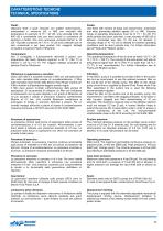
CARATTERISTICHE TECNICHE TECHNICAL SPECIFICATIONS Fluidi: Utilizzare fluidi a base minerale con additivi anticorrosione, antiossidanti e antiusura (HL o HM) con viscosità alla temperatura di esercizio di 15 ÷ 40 cSt. Una viscosità limite di 800 cSt è ammissibile solo per brevi periodi in condizione di partenza a freddo. Non sono ammesse viscosità inferiori ai 10 cSt. Viscosità comprese tra i 10 e i 15 cSt sono tollerate solo in casi eccezionali e per brevi periodi. Per maggiori dettagli consultare la sezione Fluidi e Filtrazione. Fluids: Use fluids with mineral oil basis and anticorrosive, antioxidant...
Open the catalog to page 3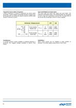
Capacità di carico albero d’ingresso: L'albero d’ingresso è in grado di sopportare sia carichi radiali sia assiali. I carichi massimi ammissibili riportati in tabella sono tali da garantire una durata dei supporti superiore all'80% della durata in assenza di carichi. Input shaft Radial and Axial loads: The input shaft can stand both radial and axial loads. The maximum permissible loads in the following table are calculated in such a way as to guarantee a service life of at least 80% of the service life of bearings to which no load is applied. Cilindrata / Displacement Forza radiale Radial load...
Open the catalog to page 4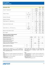
DATI TECNICI TECHNICAL DATA Dimensione / Size picco / peak Portata massima a nmax / Max flow at nmax Pressione / Pressure Potenza massima / Maximum power Cont. (pnom) picco/peak (pmax) Momento di inerzia / Moment of inertia Coppia massima a Vg max / Max torque at Vg max Dati tecnici pompa sovralimentazione Charge pump technical data cm3/giro [in3/rev] Cilindrata pompa di sovralimentazione Displacement charge pump Pressione di taratura sovralimentazione Charge pump setting pressure Pressione massima sovralimentazione Charge pump maximum pressure Potenza Cont. pompa sovralimentazione a 3400 rpm...
Open the catalog to page 5
CODICI DI ORDINAZIONE ORDERING CODE The following alphanumeric codes system has been developed to identify all of the configuration options for the S6CV 75 pumps. Use the model code below to specify the desired features. All alphanumeric digits system of the code must be present when ordering. We recommend to carefully read the catalogue before filling the ordering code. Le seguenti lettere o numeri del codice, sono state sviluppate per identificare tutte le configurazioni possibili delle pompe S6CV 75. Usare il seguente modulo per identificare le caratteristiche desiderate. Tutte le lettere...
Open the catalog to page 6
7 - POMPA DI SOVRALIMENTAZIONE / CHARGE PUMP 00 18 23 27 Senza pompa di sovralimentazione Without charge pump Cilindrata 18 cm3/giro Displacement [1.098 in3/rev] Cilindrata 23.1 cm3/giro Displacement [1.41 in3/rev] Cilindrata 27.3 cm3/giro Displacement [1.647 in3/rev] Manuale a leva retroazionato Manual lever with feed-back Manuale a leva retroazionato con sensore di posizione neutra Manual lever with feed-back with neutral position micro switch Idraulico proporzionale retroazionato Hydraulic proportional with feed-back Idraulico proporzionale non retroazionato Hydraulic proportional without...
Open the catalog to page 7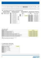
12A - CARATTERISTICA VALVOLA DI TAGLIO / Senza Valvola di Taglio (XX) (XX) Without Cut-Off Valve Caratteristica non necessaria Feature not necessary Valvola Taglio elettrico (TE) (TE) Electric Cut-Off Valve Compensatore di pressione (PC) (PC) Pressure Compensator Bloccata / Locked Pressione di taratura Pressure Setting Valvola Taglio elettrico + pressione (EP) (EP) Pressure Compensator + Electric Cut-Off Tensione Voltage Tensione Voltage Bloccata / Locked Pressione di taratura Pressure Setting Senza Filtro Without Filter Con sensore ottico d’intasamento (8 bar) Optical clogging sensor [116 psi]...
Open the catalog to page 8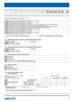
Predisposizioni per assemblaggio 2a Pompa da parte di Brevini Fluid Power Through drive for 2ndPump assembled by Brevini Fluid Power Predisposizione Tandem per assemblaggio mediante SAE A = Z9 - 16/32 DP Tandem through drive with flange SAE A = 9T - 16/32 DP Predisposizione Tandem per assemblaggio mediante SAE B = Z13 - 16/32 DP Tandem through drive with flange SAE B = 13T - 16/32 DP Predisposizione Tandem per assemblaggio mediante SAE B-B = Z15 - 16/32 DP (Speciale per pompe S5AV 032/045/050/063) Tandem through drive with flange SAE B-B = 15T - 16/32 DP (Special for S5AV 032/045/050/063 pumps)...
Open the catalog to page 9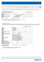
Tensione di alimentazione Voltage Diametro Grani Strozzatori(1) Control orifices Diameter(1) Regolatore / Control Indicare la tensione e il diametro del grano To indicate the Voltage and the Control orifices diameter 12 24 HER 12 24 STANDARD Senza grano strozzatore Without control orifices Ø 0.8 [Ø 0.031] Ø 1.2 [Ø 0.047] 1) in caso di richieste di differenti tempi di risposta, rivolgersi al reparto commerciale in case of the different response times, please you contact sales office Regolatore HME - HMI Control Indicare tipo di Inching, tensione (solo HME), Diametro grani strozzatori, Valvola...
Open the catalog to page 10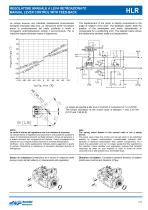
REGOLATORE MANUALE A LEVA RETROAZIONATO MANUAL LEVER CONTROL WITH FEED-BACK La pompa assume una cilindrata direttamente proporzionale all'angolo impostato dalla leva. La retroazione sente l'eventuale errore di posizionamento del piatto oscillante e tende a correggerlo automaticamente tramite il servocomando. Per la relazione angolo-cilindrata vedere il diagramma. The displacement of the pump is directly proportional to the angle of rotation of the lever. The feedback system feels the position of the swashplate and works automatically to compensate for a positioning error. The diagram below shows...
Open the catalog to page 11All Brevini Power Transmission catalogs and technical brochures
 S series
164 Pages
 Slewing drives
112 Pages
 BGM
BGM18 Pages
 S6CV
S6CV64 Pages
 MEDIUM PRESSURE MOTORS AND PUMPS
124 Pages
 series 498
2 Pages
 series 492
2 Pages
 series 392/393
2 Pages
 SH11C
SH11C24 Pages
 H1C
H1C18 Pages
 INDUSTRIAL SERIES
260 Pages
 LEONESSA BREVINI
57 Pages
 Hand pumps
40 Pages
 Valves and Electronics
274 Pages
 VPS Mobile Valves
68 Pages
 MC Tubes kit / Kit tub
38 Pages
 MC Hydraulic power pack
64 Pages
 FP Hydraulic power pack
100 Pages
 MB Orbital geared motors
20 Pages
 Low speed high torque Orbital Motors
192 Pages
 Axial piston Pumps and Motors
530 Pages
 Rotary Drilling
5 Pages
 Bulk Mining Industrail
11 Pages
 Deck Crane Brochure
5 Pages
 Off-highway Product Range
13 Pages
 Hoisting and Recovery Winches
125 Pages
 MOBILE SLEWING DRIVES
106 Pages
 SU IM SERIES
40 Pages
 ML B RD SERIES
48 Pages
 MR
MR4 Pages
 MP
MP1 Page
 MC
MC38 Pages
 MB
MB20 Pages
 BFP
BFP4 Pages
 M series
408 Pages
 K series
488 Pages
 V series
224 Pages
 Hoisting&Recovery Winches
115 Pages
 WINCH DRIVES
16 Pages
 INDUSTRIAL PLANETARY GEARBOXES
260 Pages
 ASu Series
3 Pages
 ASu66 Series
3 Pages
 SP MkII Series
2 Pages
 TAC MkII Series
2 Pages
 TLu Series
2 Pages
 TLu66 series
2 Pages
 VT Series
8 Pages
 MC4 Series
8 Pages
 MC2 Series
8 Pages
 Powerpacks
4 Pages
 FP Series
80 Pages
 Take Up Winches for mining
16 Pages
 S Series Big
20 Pages
 Marine Technologies
14 Pages
 Winches overview
16 Pages
 Sugar mill drives
22 Pages
 Hydraulic Cylinders
2 Pages
 OT Silent Plus Pumps
10 Pages
 OT 300 Group 3 pumps
68 Pages
 OT 200 Group 2 pumps
127 Pages
 OT 100 Group 1 pumps
84 Pages
 SH11C Pumps
20 Pages
 SH5AV Pumps
28 Pages
 MD10V Pumps
99 Pages
 BRZ Orbital Motors
10 Pages
 HT Orbital Motors
19 Pages
 HR Orbital Motors
27 Pages
 AR - ARS Orbital Motors
22 Pages
 BR-BS Orbital Motors
30 Pages
 BGM Orbital Motors
19 Pages
 BG-BH Orbital Motors
31 Pages
 SH7VR Series
49 Pages
 SH7V Series
74 Pages
 MD11V Series
13 Pages
 SH11CR Series
16 Pages
 SH11C Series
24 Pages
 Twin Screw Extruder Drives
12 Pages
 Planetary Bevel Helical Posiplan
125 Pages
 S-Series Planetary Gearboxes
162 Pages
 Industrial Planetary Gearboxes
260 Pages
 Yaw and Pitch Drives
106 Pages
 Planetary wheel drives
129 Pages
 Helical & Bevel helical Gearboxes
171 Pages
 Lifting / Hoisting Gearboxes
37 Pages
 Long Travel Drives
12 Pages
 Conveyor Drives
12 Pages
 Single Screw Extruder Drives
115 Pages
 Injection Molding Drives
12 Pages
 Recovery winches
115 Pages
 Winch drives
108 Pages
 Atex Gearboxes Catalogue
30 Pages
 Slewing drives
110 Pages
 S-Series
160 Pages
 Catalog
250 Pages



Archived catalogs
 E series_2019
272 Pages
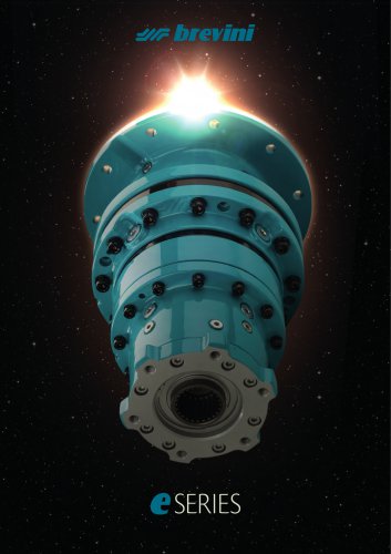 E Series
5 Pages
 CATALOGUE E series
274 Pages
- Electric gearmotor
- Planetary gearbox
- Coaxial gearhead
- Right angle gearhead
- Compact gearhead
- Solid-shaft gearhead
- Hollow-shaft gearhead
- Winch
- Gear train gear reducer
- Gearbox for industrial applications
- Transmission gearhead
- Multi-stage gearhead
- Single-stage gearhead
- AC gear-motor
- Right angle electric gearmotor
- Coaxial gearmotor
- Shaft gearhead
- Solid-shaft gear-motor
- Helical gear gearhead
- Dual-stage gearbox