- Catalogs
- Brevini Power Transmission
- ML B RD SERIES
- Products
- Catalogs
- News & Trends
- Exhibitions
ML B RD SERIES
1 /48Pages

ML B RD SERIES
1 /48Pages
Catalog excerpts

Technical Catalogue January
Open the catalog to page 1
Motion Systems ML52/B Speed increaser gearbox with through-shaft for pumps GR.2/3 © 2018 Dana Brevini S.p.A. all rights reserved. Hydr-App, SAM Hydraulik, Aron, Brevini Hydraulics, BPE Electronics, VPS Brevini, OT Oiltechnology, logos are trademarks or are registered trademarks of Dana Brevini S.p.A. or other companies Dana in Italy and other countries. The technical features supplied in this catalogue are non binding and no legal action can be taken against such material. Dana Brevini will not be held responsible for information and specifications which may lead to error or incorrect interpretations....
Open the catalog to page 3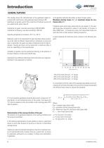
Motion Systems GENERAL FEATURES This catalog shows the characteristics of the gearboxes (speed in-creasers) ML and B series, and gearboxes (speed reducers) RD. Gearboxes are gerally used for the connection of hydraulic pump with low speed tractor power take-off. Calculation for gears was done according to UNI ISO 6336. Calculation for bearing was done according to ISO 281. Operating temperature is between -20 °C to + 85 °C. Materials used for the components of gear have been chosen according to the study of different requirements of resistance to stress and wear. In particular, the gears are...
Open the catalog to page 4
Motion Systems Example of calculation of gearboxes duration: Speed increaser ML32 - transmission ratio 1: 2.5 - rpm 1000 Operating torque:: Duty cycles: In diagram curve number 7 has to be considered (gear ratio 1: 2.5 at 1000 rpm). The estimated duration of the average torque of 60.4 Nm is approximately 3600 hours. Lubricating oil The types of oil, in the following table, are those suggested for the For features that are outside the range of proposed values, please correct lubrication of the gears and are differentiated according to the contact our sales department. temperature at which gearboxes...
Open the catalog to page 5
Pump side SPEED INCREASER GEARBOX FOR PUMPS GR.2 WITH EUROPEAN UNIFIED FLANGE ORDERING CODE ML32 = Speed increaser (aluminium body) P.T.O. 1 = Male 1” 3/8 DIN 9611 2 = Female 1” 3/8 DIN 9611 3 = Female 1” 3/8 DIN 9611 + tightening 12 = Female 1” 3/8 DIN 9611 short 18 = Female z21 - 16/32 DIN 9611 19 = Female z21 - 16/32 DIN 9611 + tightening Coupling for pump to be required to our sales department.
Open the catalog to page 6
Motion Systems TECHNICAL DATA Mounting positions Average torque on pinion (Cm) Transmission ratio * Maximum torque on pump: C1= maximum starting torque; C2= maximum torque for continuous duty.
Open the catalog to page 7
ML52 SPEED INCREASER GEARBOX FOR PUMPS GR.2/3 WITH EUROPEAN UNIFIED FLANGE Pump side ORDERING CODE ML52 = Speed increaser (aluminium body) P.T.O. 1 = Male 1” 3/8 DIN 9611 2 = Female 1” 3/8 DIN 9611 3 = Female 1” 3/8 DIN 9611 + tightening 12 = Female 1” 3/8 DIN 9611 short 18 = Female z21 - 16/32 DIN 9611 19 = Female z21 - 16/32 DIN 9611 + tightening Coupling for pump to be required to our sales department. Flange Omit for pumps GR.3 C = predisposition for pumps GR.2 - GR.3 S = SAE A - see page 30 T = SAE B - see page 30 Mounting positions 1/2/3/4 Transmission ratio 1 = 1 : 1.0 1,5 = 1 : 1.5 2...
Open the catalog to page 8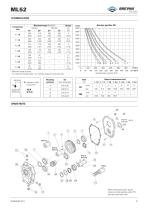
Motion Systems TECHNICAL DATA Mounting positions Transmission ratio * Maximum torque on pump: C1= maximum starting torque; C2= maximum torque for continuous duty.
Open the catalog to page 9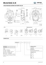
ML52/SAE A-B SPEED INCREASER GEARBOX FOR PUMPS SAE A/B 200 [7.874] Pump side ORDERING CODE ML52/SAE A = Speed increaser (aluminium body) ML52/SAE B = Speed increaser (aluminium body) P.T.O. 1 = Male 1” 3/8 DIN 9611 2 = Female 1” 3/8 DIN 9611 3 = Female 1” 3/8 DIN 9611 + tightening 12 = Female 1” 3/8 DIN 9611 short 18 = Female z21 - 16/32 DIN 9611 19 = Female z21 - 16/32 DIN 9611 + tightening Input shaft 9 = Female Ø 25 16 = Female Z18 DIN 5482 (35x31) Coupling for pump to be required to our sales department.
Open the catalog to page 10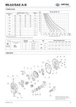
Motion Systems TECHNICAL DATA Transmission ratio * Maximum torque on pump: C1= maximum starting torque; C2= maximum torque for continuous duty. Mounting positions
Open the catalog to page 11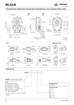
ML52/B SPEED INCREASER GEARBOX WITH THROUGH-SHAFT FOR PUMPS GR.2/3 WITH EUROPEAN UNIFIED FLANGE Pump side Mounting positions ORDERING CODE ML52B = Speed increaser (aluminium body) P.T.O. 4 = Female/Female Ø 35 short 6 = Male/Male 1” 3/8 DIN 9611 7 = Female/Female 1” 3/8 DIN 9611 8 = Female/Male 1” 3/8 DIN 9611 15 = Female/Female 1” 3/8 DIN 9611 short 23 = Male 50x45 Z=24 DIN 5482 Male 1” 3/8 DIN 9611 Coupling for pump to be required to our sales department.
Open the catalog to page 12
Motion Systems TECHNICAL DATA Mounting positions Average torque on pinion (Cm) Transmission ratio * Maximum torque on pump: C1= maximum starting torque; C2= maximum torque for continuous duty.
Open the catalog to page 13
B-585/A SPEED INCREASER GEARBOX FOR PUMPS SAE A 20.5 [0.807] Pump side ORDERING CODE B-585/A - ** -1/ *** - * - ** - ** - ** B-585/A = Speed increaser for pumps SAE A P.T.O. 1 = Male 1” 3/8 DIN 9611 3 = Female 1” 3/8 DIN 9611 + tightening 19 = Female z21 - 16/32 DIN 9611 + tightening Variants 00 = No variant Coupling 00 = No Coupling 02 = Z=18 BF3/2 2T = Z=18 BF3/2T 03 = Z=18 BF3 Pinion internal teeth A0 = Z13 16/32” B0 = Z15 16/32” C0 = Z18 DIN 5482 (from 1/1.0 to 1/3.8 transmission ratio) Mounting positions 1/2/3
Open the catalog to page 14
Motion Systems TECHNICAL DATA Transmission ratio * Maximum torque on pump: C1= maximum starting torque; C2= maximum torque for continuous duty. Average torque on pinion (Cm) Mounting positions
Open the catalog to page 15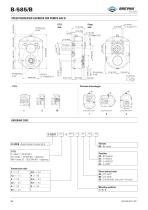
B-585/B SPEED INCREASER GEARBOX FOR PUMPS SAE B 121 [4.764] Pump side ORDERING CODE B-585/B - ** -1/ *** - * - ** - ** - ** B-585/B = Speed increaser for pumps SAE B P.T.O. 1 = Male 1” 3/8 DIN 9611 3 = Female 1” 3/8 DIN 9611 + tightening 19 = Female z21 - 16/32 DIN 9611 + tightening Variants 00 = No variant Coupling 00 = No Coupling 02 = Z=18 BF3/2 2T = Z=18 BF3/2T 03 = Z=18 BF3 Pinion internal teeth A0 = Z13 16/32” B0 = Z15 16/32” C0 = Z18 DIN 5482 (only until 1/3.8 ratio)
Open the catalog to page 16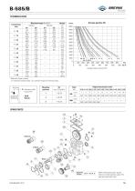
Motion Systems TECHNICAL DATA Transmission ratio * Maximum torque on pump: C1= maximum starting torque; C2= maximum torque for continuous duty. Average torque on pinion (Cm) Mounting positions
Open the catalog to page 17All Brevini Power Transmission catalogs and technical brochures
 S series
164 Pages
 Slewing drives
112 Pages
 BGM
BGM18 Pages
 S6CV
S6CV64 Pages
 MEDIUM PRESSURE MOTORS AND PUMPS
124 Pages
 series 498
2 Pages
 series 492
2 Pages
 series 392/393
2 Pages
 SH11C
SH11C24 Pages
 H1C
H1C18 Pages
 INDUSTRIAL SERIES
260 Pages
 LEONESSA BREVINI
57 Pages
 Hand pumps
40 Pages
 Valves and Electronics
274 Pages
 VPS Mobile Valves
68 Pages
 MC Tubes kit / Kit tub
38 Pages
 MC Hydraulic power pack
64 Pages
 FP Hydraulic power pack
100 Pages
 MB Orbital geared motors
20 Pages
 Low speed high torque Orbital Motors
192 Pages
 Axial piston Pumps and Motors
530 Pages
 Rotary Drilling
5 Pages
 Bulk Mining Industrail
11 Pages
 Deck Crane Brochure
5 Pages
 Off-highway Product Range
13 Pages
 Hoisting and Recovery Winches
125 Pages
 MOBILE SLEWING DRIVES
106 Pages
 SU IM SERIES
40 Pages
 MR
MR4 Pages
 MP
MP1 Page
 MC
MC38 Pages
 MB
MB20 Pages
 BFP
BFP4 Pages
 M series
408 Pages
 K series
488 Pages
 V series
224 Pages
 Hoisting&Recovery Winches
115 Pages
 WINCH DRIVES
16 Pages
 INDUSTRIAL PLANETARY GEARBOXES
260 Pages
 ASu Series
3 Pages
 ASu66 Series
3 Pages
 SP MkII Series
2 Pages
 TAC MkII Series
2 Pages
 TLu Series
2 Pages
 TLu66 series
2 Pages
 VT Series
8 Pages
 MC4 Series
8 Pages
 MC2 Series
8 Pages
 Powerpacks
4 Pages
 FP Series
80 Pages
 Take Up Winches for mining
16 Pages
 S Series Big
20 Pages
 Marine Technologies
14 Pages
 Winches overview
16 Pages
 Sugar mill drives
22 Pages
 Hydraulic Cylinders
2 Pages
 OT Silent Plus Pumps
10 Pages
 OT 300 Group 3 pumps
68 Pages
 OT 200 Group 2 pumps
127 Pages
 OT 100 Group 1 pumps
84 Pages
 S6CV Pumps
68 Pages
 SH11C Pumps
20 Pages
 SH5AV Pumps
28 Pages
 MD10V Pumps
99 Pages
 BRZ Orbital Motors
10 Pages
 HT Orbital Motors
19 Pages
 HR Orbital Motors
27 Pages
 AR - ARS Orbital Motors
22 Pages
 BR-BS Orbital Motors
30 Pages
 BGM Orbital Motors
19 Pages
 BG-BH Orbital Motors
31 Pages
 SH7VR Series
49 Pages
 SH7V Series
74 Pages
 MD11V Series
13 Pages
 SH11CR Series
16 Pages
 SH11C Series
24 Pages
 Twin Screw Extruder Drives
12 Pages
 Planetary Bevel Helical Posiplan
125 Pages
 S-Series Planetary Gearboxes
162 Pages
 Industrial Planetary Gearboxes
260 Pages
 Yaw and Pitch Drives
106 Pages
 Planetary wheel drives
129 Pages
 Helical & Bevel helical Gearboxes
171 Pages
 Lifting / Hoisting Gearboxes
37 Pages
 Long Travel Drives
12 Pages
 Conveyor Drives
12 Pages
 Single Screw Extruder Drives
115 Pages
 Injection Molding Drives
12 Pages
 Recovery winches
115 Pages
 Winch drives
108 Pages
 Atex Gearboxes Catalogue
30 Pages
 Slewing drives
110 Pages
 S-Series
160 Pages
 Catalog
250 Pages


Archived catalogs
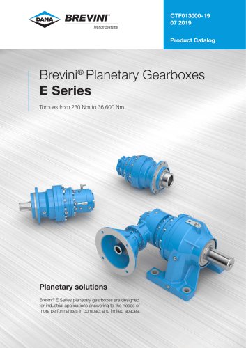 E series_2019
272 Pages
 E Series
5 Pages
 CATALOGUE E series
274 Pages
- Electric gearmotor
- Planetary gearbox
- Coaxial gearhead
- Right angle gearhead
- Compact gearhead
- Solid-shaft gearhead
- Winch
- Gear train gear reducer
- Hollow-shaft gearhead
- Gearbox for industrial applications
- Transmission gearhead
- Right angle electric gearmotor
- Multi-stage gearhead
- Shaft gearhead
- Single-stage gearhead
- Coaxial gearmotor
- AC gear-motor
- Helical gear gearhead
- Solid-shaft gear-motor
- Gear train gearmotor