- Catalogs
- Brevini Power Transmission
- MC Hydraulic power pack
- Products
- Catalogs
- News & Trends
- Exhibitions
MC Hydraulic power pack
1 /64Pages

MC Hydraulic power pack
1 /64Pages
Catalog excerpts

MC HYDRAULIC POWER PACK Technical Catalogue January
Open the catalog to page 1
© 2018 Dana Brevini S.p.A. all rights reserved. Hydr-App, SAM Hydraulik, Aron, Brevini Hydraulics, BPE Electronics, VPS Brevini, OT Oiltechnology, logos are trademarks or are registered trademarks of Dana Brevini S.p.A. or other companies Dana in Italy and other countries. The technical features supplied in this catalogue are non binding and no legal action can be taken against such material. Dana Brevini will not be held responsible for information and specifications which may lead to error or incorrect interpretations. Given the continuous technical research aimed at improved technical features...
Open the catalog to page 3
Motion Systems Operating pressure is controlled by the maximum pressure valve and the type of pump used (in terms of performance) may be determined by the maximum pressure valve. Therefore, it is essential not to change the maximum pressure valve. If neccessary, contact our technical service department. 1) The power pack must be mounted using the M10 holes on the endhead. 2) The power pack must not come into contact with sheet metal, protective guards or any parts that may vibrate and transmit noise. 3) The ports on the endhead have been identified by the letters A-B -C. The hydraulic connection...
Open the catalog to page 4
Endhead configuration Power pack endhead configuration 4 Flow control valve The possible configurations of the MC power pack are determined by the body machining. MCA flange allows the mounting of controls and flow regulators in the cavity 3 and fixeed setting flow control valve on cavity 4.
Open the catalog to page 5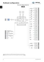
Endhead configuration Power pack endhead configuration The possible configurations of the MC power pack are determined by the body machining. MCA flange allows the mounting of controls and flow regulators fixed setting in the cavity 3.
Open the catalog to page 6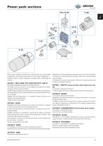
Power pack sections VIII (J-K-W) With its great modularity, the MC series of power packs can create multiple configurations which satisfy requirements in a wide range of applications. To make it easier to choose components, the power pack is subdivided into sections. SECTION I - SERIE, FLANGE TYPE, VALVES ON CAVITY 1 AND 1R MC Series Powerpacks are based on the Flange features. The Flange is the core of the unit, on the flange are mounted all the valves, the pump, the motor and the reservoir. The MC Flange is available in several Versions (with different tooling options). The Flange Version must...
Open the catalog to page 7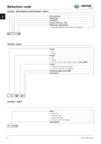
Motion Systems SECTION I - SERIE, ENDHEAD, VALVES ON CAVITY 1 AND 1R
Open the catalog to page 8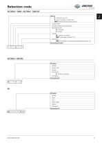
Motion Systems SECTION IV- TANKS /SECTION V - TUBES KIT
Open the catalog to page 9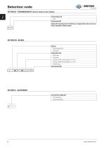
Selection code SECTION VII - TRANSMISSION KIT (only for motors on the catalog) Transmission kit Type End section VII Specify the transmission kit whether you requested the joint and accessories assembly (without motor). T ** - SECTION VIII - BLOCKS Blocks Mounting position Accessory Separation line Block type Accessory Pressure relief valve setting on “A” line Pressure relief valve setting on “B” line CETOP valve End section VIII J SECTION IX - ACCESSORIES Accessories (optional) First accessory Second accessory
Open the catalog to page 10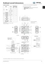
Motion Systems The number of cavities tooled identify the endhead type: There are three types of cavities: - Peripheral cavities, which can be accessed externally - Return cavities, inside of the tank. - Ports POWER PACK FIXING SIDE PUMP/TANK SIDE On the endhead are highlighted (P-T) ports. In the drawing are shown the common dimensions.
Open the catalog to page 11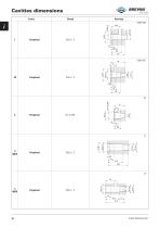
Cavities dimensions Cavity
Open the catalog to page 12
Motion Systems The machining of the cavity 3 and the P-T ports define the body type.
Open the catalog to page 13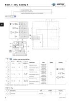
* Pressure relief valve direct-acting * 1 = Supplied assembled. Unassembled, see accessories page 59
Open the catalog to page 14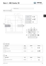
Motion Systems
Open the catalog to page 15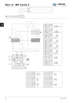
Motion Systems
Open the catalog to page 16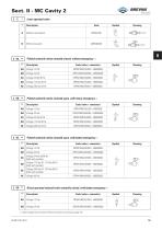
Motion Systems Lever operated valve * Piloted solenoid valves normally closed, without emergency m ** Piloted solenoid valves normally open, with rotary emergency in ** Piloted solenoid valves normally open, with button emergency in ** Direct operated solenoid valve normally closed, with button emergency m ** 1 = Valves supplied with connector. Without connector see accessories page 59
Open the catalog to page 17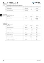
Motion Systems Bidirectional flow control valves not compensated Button operated valves
Open the catalog to page 18
Sect. II - MCA Cavity 3 Cavity Type Features Components only for MCA MC A
Open the catalog to page 19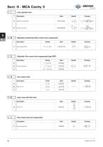
MCA Sect. II - MCA Cavity 3 3 FB * Adjustable unidirectional flow control valve compensated Adjustable flow control valve compensated (type VRFE) Screw adjustment Flow control valve Logic valve with chek valve Flow control valve not compensated
Open the catalog to page 20
Motion Systems
Open the catalog to page 21
Sect. II - MCB Cavity 3 Cavity Type Features Flow control valves Components only for MCB MC B Flow control valve Plug with flow control valve Flow Code (flow control valve) Code (kit plug + washer)
Open the catalog to page 22
Fitting on return cavity 4 Flow control valve on fitting 4 Omit if not required Components only for MCA H Any fitting and flow control valve on cavity 4 Fitting and flow control valve /*
Open the catalog to page 23
Motion Systems Cornbinstions plugs on ports P-T Symbols description
Open the catalog to page 24
P2 = Intermittent operating pressure Tanks not compatible (as dimensions, P3 = Intermittent peak pressure (20 sec. max) see page 25).
Open the catalog to page 25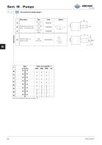
^DANA^> Motion Systems P 1 (1) ** / * Accessories for pumps group 1 Description Single-phase motor start valve - on auxiliary outlet Soft start valve - on auxiliary outlet Tanks not compatible (as dimensions, see page 25).
Open the catalog to page 26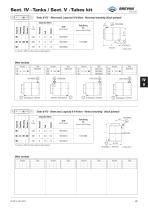
(1) Variant - OMIT if without tank but with tubes kit Other variants Variant Tanks 0175 - Sheet steel, capacity 5-6-8 liters - Vertical mounting (black painted) Capacity (1) Variant - OMIT if without tank but with tubes kit Other variants Variant
Open the catalog to page 29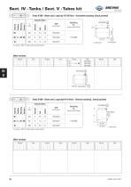
(1) Variant - OMIT if without tank but with tubes kit Other variants Tanks 0200 - Sheet steel, capacity5-8-10 liters - Vertical mounting (black painted) (1) Variant - OMIT if without tank but with tubes kit Other variants
Open the catalog to page 30
^DANA^> Motion Systems Tanks 0 217 - Sheet steel, capacity10-12 liters - Horizontal mounting (black painted) 220 (12 liters) (1) Variant - OMIT if without tank but with tubes kit Other variants (..) spare parts Tanks 0 217 - Sheet steel, capacity10-12 liters - Vertical mounting (black painted) Capacity (1) Variant - OMIT if without tank but with tubes kit Other variants Variant
Open the catalog to page 31All Brevini Power Transmission catalogs and technical brochures
 S series
164 Pages
 Slewing drives
112 Pages
 BGM
BGM18 Pages
 S6CV
S6CV64 Pages
 MEDIUM PRESSURE MOTORS AND PUMPS
124 Pages
 series 498
2 Pages
 series 492
2 Pages
 series 392/393
2 Pages
 SH11C
SH11C24 Pages
 H1C
H1C18 Pages
 INDUSTRIAL SERIES
260 Pages
 LEONESSA BREVINI
57 Pages
 Hand pumps
40 Pages
 Valves and Electronics
274 Pages
 VPS Mobile Valves
68 Pages
 MC Tubes kit / Kit tub
38 Pages
 FP Hydraulic power pack
100 Pages
 MB Orbital geared motors
20 Pages
 Low speed high torque Orbital Motors
192 Pages
 Axial piston Pumps and Motors
530 Pages
 Rotary Drilling
5 Pages
 Bulk Mining Industrail
11 Pages
 Deck Crane Brochure
5 Pages
 Off-highway Product Range
13 Pages
 Hoisting and Recovery Winches
125 Pages
 MOBILE SLEWING DRIVES
106 Pages
 SU IM SERIES
40 Pages
 ML B RD SERIES
48 Pages
 MR
MR4 Pages
 MP
MP1 Page
 MC
MC38 Pages
 MB
MB20 Pages
 BFP
BFP4 Pages
 M series
408 Pages
 K series
488 Pages
 V series
224 Pages
 Hoisting&Recovery Winches
115 Pages
 WINCH DRIVES
16 Pages
 INDUSTRIAL PLANETARY GEARBOXES
260 Pages
 ASu Series
3 Pages
 ASu66 Series
3 Pages
 SP MkII Series
2 Pages
 TAC MkII Series
2 Pages
 TLu Series
2 Pages
 TLu66 series
2 Pages
 VT Series
8 Pages
 MC4 Series
8 Pages
 MC2 Series
8 Pages
 Powerpacks
4 Pages
 FP Series
80 Pages
 Take Up Winches for mining
16 Pages
 S Series Big
20 Pages
 Marine Technologies
14 Pages
 Winches overview
16 Pages
 Sugar mill drives
22 Pages
 Hydraulic Cylinders
2 Pages
 OT Silent Plus Pumps
10 Pages
 OT 300 Group 3 pumps
68 Pages
 OT 200 Group 2 pumps
127 Pages
 OT 100 Group 1 pumps
84 Pages
 S6CV Pumps
68 Pages
 SH11C Pumps
20 Pages
 SH5AV Pumps
28 Pages
 MD10V Pumps
99 Pages
 BRZ Orbital Motors
10 Pages
 HT Orbital Motors
19 Pages
 HR Orbital Motors
27 Pages
 AR - ARS Orbital Motors
22 Pages
 BR-BS Orbital Motors
30 Pages
 BGM Orbital Motors
19 Pages
 BG-BH Orbital Motors
31 Pages
 SH7VR Series
49 Pages
 SH7V Series
74 Pages
 MD11V Series
13 Pages
 SH11CR Series
16 Pages
 SH11C Series
24 Pages
 Twin Screw Extruder Drives
12 Pages
 Planetary Bevel Helical Posiplan
125 Pages
 S-Series Planetary Gearboxes
162 Pages
 Industrial Planetary Gearboxes
260 Pages
 Yaw and Pitch Drives
106 Pages
 Planetary wheel drives
129 Pages
 Helical & Bevel helical Gearboxes
171 Pages
 Lifting / Hoisting Gearboxes
37 Pages
 Long Travel Drives
12 Pages
 Conveyor Drives
12 Pages
 Single Screw Extruder Drives
115 Pages
 Injection Molding Drives
12 Pages
 Recovery winches
115 Pages
 Winch drives
108 Pages
 Atex Gearboxes Catalogue
30 Pages
 Slewing drives
110 Pages
 S-Series
160 Pages
 Catalog
250 Pages


Archived catalogs
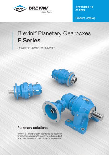 E series_2019
272 Pages
 E Series
5 Pages
 CATALOGUE E series
274 Pages
- Electric gearmotor
- Planetary gearbox
- Coaxial gearhead
- Right angle gearhead
- Compact gearhead
- Solid-shaft gearhead
- Winch
- Gear train gear reducer
- Hollow-shaft gearhead
- Gearbox for industrial applications
- Transmission gearhead
- Right angle electric gearmotor
- Multi-stage gearhead
- Shaft gearhead
- Single-stage gearhead
- Coaxial gearmotor
- AC gear-motor
- Helical gear gearhead
- Solid-shaft gear-motor
- Gear train gearmotor