
- Catalogs
- Brevini Power Transmission
- Low speed high torque Orbital Motors


- Products
- Catalogs
- News & Trends
- Exhibitions
Low speed high torque Orbital Motors

Low speed high torque Orbital Motors
Hydraulic motors convert hydraulic energy into mechanical energy. Orbital motors, specifically, use a fixed displacement mechanism involving an external stator with internal toothing and a rotor with planetary motion. There are two types of gear sets: Gerotor and Geroller, each with different configurations and applications.
- BGM: Compact Gerotor motors suitable for high-speed applications.
- BG, BH: Economical Gerotor motors for light to medium duties.
- BR, BS: Roller motors with high efficiency and good starting torque.
- ARS: Roller motors with high radial and axial load capacity.
- HR: High power roller motors with a capacity of up to 44.2 kW.
- HT: High-performance motors suitable for high torque applications, withstanding pressures up to 280 bar.
The motors' performance in terms of power, speed, and torque is depicted in histograms. Maintenance guidelines include operating within specified parameters, ensuring proper oil temperature and viscosity, and regular checks for leaks and oil levels. Proper filtration is crucial to maintain oil contamination levels within ISO 4406:1999 standards.
Motors should be filled with oil before operation, and the system should be purged of air to prevent foaming. The ambient temperature should be between -30°C and +90°C. Use of fire-resistant fluids is possible with technical consultation. Static and dynamic seals are standard in NBR, suitable for mineral oils.
Dana Brevini motors use static and dynamic seals made of NBR, suitable for mineral oils. Seals should not be exposed to temperatures outside -30°C to +90°C.
A separate drain line is necessary when back pressure exceeds acceptable levels. It is recommended for brake motors and short motors to ensure cooling and reduce shaft seal pressure.
Dana Brevini motors can operate in open or closed circuits and can be connected in series or parallel. Series connections ensure uniform speed but may suffer from leakage issues, while parallel connections provide equal torque distribution.
For braking, motors act as pumps converting mechanical energy into hydraulic energy. The braking torque is influenced by motor displacement and valve pressure settings. Proper valve selection is crucial to avoid cavitation and ensure effective braking.
Each product has an identification plate with a serial number for tracking and information requests.
The document provides conversion factors between metric and English units for various hydraulic measurements.
The document provides a detailed description of orbital motors, including a perpetual calendar for manufacturing dates and batch numbers. It outlines the product description as a 'New Solution' and includes a coding system for identifying motor configurations.
The motors have side and rear port configurations, optimized spool valve design to minimize leakage, built-in check valves, and a dust seal to protect the shaft seal. They offer a high torque/weight ratio, good low-speed performance, and options for different mounting flanges.
The document lists specifications for various motor models (BGM 013, 020, 032, 040, 050), including displacement, max input pressure, max differential pressure, max torque, max flow, max speed, and max power. It also specifies intermittent and peak conditions for pressure and torque.
Details on max permissible shaft seal pressure, max return pressure with and without drain lines, and min starting torque are provided. The document advises contacting Dana Brevini for conditions not covered in the charts.
An alphanumeric system is used to specify motor configurations, including series, displacement, version, shaft end, main port, valve, valve feature, option, version feature, and painting.
Dimensions and weights for different motor versions (FR0/FRQ and SP1) are provided, along with main port thread depths.
Details on flange and shaft dimensions, including splined and cylindrical shaft options, are included.
Performance curves for BGM/FRQ motors with a fixed flow restrictor are provided, showing torque/speed relationships.
The TAC-E sensor kit includes an inductive sensor with specific technical features such as number of pulses per revolution, voltage, max load, frequency, temperature range, and enclosure rating.
Information on permissible shaft loads and recommended tightening torques for various fittings is included.
The document provides detailed specifications for the BH series hydraulic motors, including models BH 050, BH 080, BH 100, BH 130, BH 160, BH 200, BH 250, BH 315, and BH 400. Each model is characterized by its displacement, maximum speed, and power output. The motors are designed for continuous, intermittent, and peak operations with specific limits on duration.
- Max Speed: Ranges from 165 to 225 rpm depending on the model.
- Max Power: Varies from 47.8 kW to 382.5 kW across different models.
- Torque: Continuous torque ranges from 140 Nm to 360 Nm.
- Intermittent duty should not exceed 10% of each minute.
- Peak duty should not exceed 1% of each minute.
- Case pressure without a drain line is the average of inlet and return pressure.
- Max permissible return pressure with a drain line is 138 bar.
- Motors are available in various configurations identified by a model code.
- Options include different shaft types, mounting flanges, and seal versions.
- Dimensions and weights are provided for each model, with specific measurements for length and weight.
- Radial load capacity is dependent on speed and distance from the mounting flange.
- Specific formulas are provided for calculating permissible loads.
- Exceeding continuous pressure or flow values should not occur simultaneously.
The document outlines the specifications for orbital motors, highlighting features such as pressure compensated valve plates for minimal leakage, 7-socket roller sets, and options for heavy shaft loads. It includes built-in check valves for high discharge pressures without a connected drain line.
The ordering code section provides details on displacement options ranging from 50 to 400 cm3/rev, mounting options with different bolt configurations, and additional options like high-pressure seals, brake motors, and electronic tachometers.
Tests were conducted using oil with a viscosity of 37 cSt at 45°C. The document provides detailed specifications for various motor displacements, including maximum input pressure, differential pressure, torque, flow, speed, and power. It also specifies conditions for continuous, intermittent, and peak operations.
Maximum return pressure without a drain line is specified for different motor series (ARS, ARSW, ARF), with conversions provided for bar to psi. Minimum starting torque is detailed for continuous and intermittent conditions.
Dimensions and weights are provided for different motor series (ARS, ARSW, ARF) with specific measurements for various components. The document also includes thread depth specifications for main ports and drain motors.
The ARF and FP motors include a multi-plate disc brake that is hydraulically released. This brake is suitable for static braking actions like parking or safety brakes. Dynamic braking should be achieved through the hydraulic circuit, and high rotation speeds or prolonged vertical operations may require consultation with Dana Brevini's technical department.
The document outlines the specifications for ARF and FP brakes used in hydraulic motors. Key parameters include minimum release pressure, complete brake release pressure, maximum pressure, and maximum static torque. The ARF brake requires 80 cm3 of hydraulic oil, while the FP brake has a maximum motor speed of 350 rpm.
For FP motors, the drain port must be connected to the tank to prevent overheating. ARF motors should use heat-resistant hydraulic oils with specific viscosity grades. In open circuit systems, a flow control valve is recommended to prevent dynamic braking.
The document describes typical configurations for open and closed loop systems, including single and dual brake-motor setups. These configurations are used in various machinery like cranes and sweepers, emphasizing automatic brake operation and the use of overcentre valves for controlled stopping.
Details on dimensions and assembly are provided, including warnings about the tacho shaft speed and load capacities. The document specifies that electronic sensors are not supplied with the motors and must be ordered separately.
The document provides detailed technical data for various BR motor models, including displacement, maximum input pressure, maximum torque, and speed. It highlights the importance of not exceeding continuous pressure and flow values simultaneously.
Load diagrams are included to illustrate the maximum static and radial loads the bearings can handle, depending on axial load conditions.
This document provides detailed technical specifications for BS motors with various shaft configurations, including cylindrical and splined shafts. It outlines the permissible radial shaft load, which depends on speed, distance from the load point to the mounting flange, and the version of the flange and shaft. The formula for calculating radial load is valid for speeds greater than or equal to 200 rpm, with a maximum permissible load of 8000 N for speeds below 200 rpm.
The document includes comprehensive data for different motor models (BS 050, BS 080, BS 100, etc.), specifying displacement, maximum input pressure, maximum differential pressure, maximum torque, maximum flow, maximum speed, and maximum power. It also highlights the conditions for intermittent and peak duty, which should not exceed 10% and 1% of each minute, respectively.
The case pressure without a drain line is the average between inlet and return pressure. The motors are supplied with a standard drain port, and the maximum permissible return pressure with a drain line is 175 bar. The document advises contacting Brevini Fluid Power for conditions not covered by the provided charts.
An alphanumeric system is used to identify all configuration options for BS motors. The document provides a detailed guide on how to specify desired features using the model code, emphasizing the importance of including all code digits when ordering.
Dimensions and weights for various motor models are provided, including measurements for different flange types and shaft configurations. The document specifies the maximum thread depth for motor drain ports, which varies depending on the version.
The document includes formulas for calculating radial load capacity based on speed and distance from the flange, applicable to different flange types. It reiterates the conditions under which the formulas are valid and the maximum permissible load for speeds below 200 rpm.
It is noted that exceeding continuous pressure or flow values should not occur simultaneously. This section emphasizes the importance of adhering to specified operational limits to ensure motor performance and longevity.
- Diametral pitch: 12/24
- Number of teeth: 12
- Pitch diameter: 25.4 mm
- Pressure angle: 30°
- Module: 2.1166
- Minor diameter: 23.0 mm
- Major diameter: 28.0 mm
- Max measurement between pins: 17.62 mm
- Pins diameter: 4.835 mm
- Finished dimensions after hardening: +0.033 to -0.1 mm
- ANS B 92.1 + 1970 Class 5
- Corrected m·x=0.8
- HR Motor “C” and “M” versions
- Cylindrical and splined shafts with various max admissible torques ranging from 300 Nm to 860 Nm
- Various thread depths and types for different versions (S, C, W, L, F, M)
- Special cover required for flushing valve on motors with “M09 - S09” ports
- Secondary drain port options for S-W versions
- F and L versions with multidisc pressure released brakes
- Static braking torque specifications
- Closed loop and open loop systems for various applications (sweepers, mobile machines, slew drives)
- Automatic brake operation and variable pump configurations
- Bearing life L10h of 1600 hours at 200 rpm
- Maximum radial load capacity under static load conditions
- Exceeding continuous pressure or flow values should not occur simultaneously
The document provides performance data for standard motors, emphasizing the use of the LW (Low Leakage) version for enhanced performance when the motor operates with a flow rate below 10 l/min (2.64 U.S. gpm). It is crucial not to exceed continuous pressure and flow values simultaneously.
The motors are designed with a heavy-duty roller type stator for high pressure and longevity. They include separate disc valves for precise phase control and built-in check valves for fluid recirculation. The shaft is supported by robust tapered roller bearings for high radial load capacity.
The document lists various models (HT 160, HT 200, HT 250, HT 315, HT 400, HT 500) with specifications such as displacement, maximum input pressure, differential pressure, torque, flow, speed, and power. It also details intermittent and peak duty conditions, oil viscosity, and minimum starting torque.
Maximum permissible shaft seal pressure is outlined, with options for standard and high-pressure seals. Pressure loss data is provided based on tests with specific oil viscosity.
A detailed alphanumeric system is provided to specify motor configurations, including series, displacement, version, flange, shaft end, main port, seals, valves, and additional options. The document advises consulting the catalogue before ordering.
Options for flushing valves and pressure relief valves are available, with specific configurations and pilot ratios. The document also mentions painting and other optional features.
- Maximum working pressure: 315 bar (4567 psi)
- Maximum flow: 40 l/min (10.5 U.S. gpm)
- Weight: 2.1 kg (4.62 lb)
- Code: P15111618
- Manifold (Base Block) BFL 1 is compatible with AR, BR, BG motors.
- Various types of bushings are listed with their dimensions and codes, suitable for different configurations.
Dana Brevini S.p.A.
Via Luciano Brevini 1/a, 42124 Reggio Emilia
Tel. +39 0522 270711
Fax +39 0522 270660
Website: www.dana.com/brevini
Email: [email protected]
Catalog excerpts
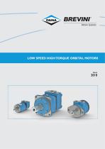
LOW SPEED HIGH TORQUE ORBITAL MOTORS
Open the catalog to page 1
Motion Systems INFORMAZIONI GENERALI/ GENERAL INFORMATION
Open the catalog to page 3
© 2018 Dana Brevini fluid power S.p.A. Tutti i diritti riservati. Hydr-App, SAM Hydraulik, Aron, Brevini Hydraulics, BPE Electronics, VPS Brevini, OT Oiltechnology, sono marchi o marchi registrati di Dana Brevini fluid power S.p.A. o da altre società del Gruppo Dana in Italia ed in altri paesi. Le caratteristiche tecniche fornite nel presente catalogo non sono impegnative e non sarà possibile basare alcun procedimento legale su tale materiale. Dana Brevini fluid power non sarà responsabile per informazioni e specifiche che possano indurre ad errori o errate interpretazioni. Data la continua ricerca...
Open the catalog to page 4
INFORMAZIONI GENERALI GENERAL INFORMATION
Open the catalog to page 5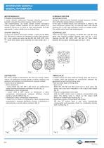
MOTORIIDRAULICI Principio di funzionamento I motori idraulici trasformano i'energia idraulica (pressione, portata) in energia meccanica (coppia, numero di giri). Tale trasformazione, nei motori orbitali avviene nell'organo motore gruppo orbitale costituito da uno statore esterno con dentatura interna ed un rotore (a moto epicicloidale) di profilo appropriato. I motori orbitali sono a cilindrata fissa. GRUPPO ORBITALE Vi sono due versioni del gruppo orbitale: i motori dei tipi BGM, BG, BH hanno lo statore con dentatura a profilo piano (gerotor: fig. 1 a-b), mentre nei motori dei tipi BR, BS, aRs,...
Open the catalog to page 6
TIPOLOGIE PRINCIPALI BGM Motori gerotor a distribuzione radiate compatti e piccola cilindrata adatti per impieghi ove siano richieste elevate velocita di rotazione ed ingombri ridotti. BG, BH Motori gerotor a distribuzione radiale. Caratterizzati da un ottimo rapporto prezzo/prestazioni, sono adatti per impieghi medi e leggeri. BR, BS Motori roller a distribuzione radiale caratterizzati da disegno compatto, elevato rendimento, ottima regolarita di rotazione e buona coppia di spunto. ARS Motori roller a distribuzione frontale compensata e con supporto dell'albero a cuscinetti. Le versioni ARS...
Open the catalog to page 7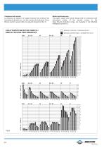
Prestazioni dei motori La potenza, la velocita e le coppie massime sia continua che intermittent! ottenibili con i vari tipi di motori di produzione Dana Brevini possono essere lette sui seguenti istogrammi (fig. 5). Motors performances The power, speed and torque ratings both for continuous and intermittent duties, of the several motors in the Dana Brevini production range, are available in the following histograms (picture 5). | | SERVIZIO CONTINUO - CONTINUOUS DUTY ^ SERVIZIO INTERMITTENTE - INTERMITTENT DUTY BREVINI Motion Systems
Open the catalog to page 8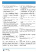
Norme generali di manutenzione ed installazione 1) I motori devono essere impiegati entro i valori previsti dai rispettivi cataloghi ed essere montati già pieni di olio soprattutto quelli di cilindrata elevata. 2) La temperatura dell'olio in funzionamento deve essere compresa normalmente da +30°C a +60°C, a temperature superiori risulta fortemente ridotta la durata dell'olio. 3) La temperatura dell'ambiente in cui è installato il motore deve essere compresa tra –30°C e +90°C. 4) Per un corretto funzionamento occorre utilizzare un olio a base minerale contenente additivi antiusura di gradazione...
Open the catalog to page 9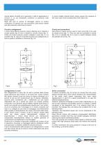
(senza albero d'uscita) ed in generale in tutte le applicazioni e versioni in cui sia necessario contenere la pressione sulla tenuta rotante. Negli altri casi le valvole di drenaggio interne al motore consentono di operare con una pressione sulla tenuta rotante pari alla pressione sulla linea di scarico. Circuiti e collegamenti I motori Dana Brevini possono essere utilizzati sia in impianti a circuito aperto (fig. 6) che in impianti a circuito chiuso (fig. 7). Inoltre piu motori possono essere collegati in serie (fig. 8), in parallelo (fig. 9), oppure e possibile passare dal collegamento in serie...
Open the catalog to page 10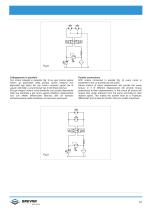
Collegamento in parallelo Con motori collegati in parallelo (fig. 9) su ogni motore agisce l'intero p disponibile dalla pompa, quindi vengono resi disponibili agli alberi dei vari motori momenti uguali (se di uguale cilindrata) o proporzionali (se di cilindrata diversa). Ad ogni singolo motore verrà distribuita una portata dipendente dalla sua cilindrata e dal carico agente all'albero realizzandosi così con effetto differenziale idraulico utile ad esempio nell'azionamento della traslazione di macchine semoventi. Parallel connections With motors connected in parallel (fig. 9) every motor is subjected...
Open the catalog to page 11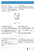
Collegamento in serie-parallelo Nel collegamento in serie parallelo (fig. 10) è possibile impiegando un secondo distributore commutare dalla disposizione in serie a quella in parallelo e viceversa realizzando in tal modo un cambio idraulico di velocità. Con la disposizione in serie si ottiene la massima velocità dei motori con coppie limitate e rinunciando all'effetto differenziale (i motori gireranno alla stessa velocità). Con la disposizione in parallelo si avranno bassa velocità, coppie elevate e l'effetto differenziale. Series parallel circuit With this configuration (fig. 10) by using an...
Open the catalog to page 12
Valvole di frenatura consigliate Per la frenatura dinamica di un carico in movimento (carico sospeso, torretta di una GRU, traslazione di un veicolo, ecc.) si possono, a seconda dell'applicazione particolare, impiegare vari tipi di valvole. Se non è indispensabile impiegare un freno meccanico a disimpegno idraulico (vedi oltre) si può impiegare semplicemente una valvola antiurto ed anticavitazione (vedi fig. 11). Qualora si intenda utilizzare un freno meccanico si può impiegare una valvola di controllo a doppio bilanciamento con selettrice del fluido in pressione (vedi fig. 12). Impiegando quest'ultimo...
Open the catalog to page 13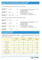
Pompe: Calcolo delle grandezze nominali / Pumps: Nominal values calculation Portata generata Q = Vg • n • % Output flow (l/min) Coppia assorbita Drive torque Potenza assorbita Driver power Vg = cilindrata geometrica (cm3/giro) / geometrical displacement (cm3/rev) Ap = caduta di pressione (bar) / drop of pressure (bar) n = velocita (rpm) / speed (rpm) Q = portata (l/min) / flow (l/min) M = coppia (Nm) / torque (Nm) W = potenza (kW) / power (kW) qv = rendimento volumetrico / volumetric efficiency qhm= rendimento idromeccanico / mech-hyd. efficiency qt = rendimento totale (gt= gv- ghm) / overall...
Open the catalog to page 14All Brevini Power Transmission catalogs and technical brochures
 S series
164 Pages
 Slewing drives
112 Pages
 BGM
BGM18 Pages
 S6CV
S6CV64 Pages
 MEDIUM PRESSURE MOTORS AND PUMPS
124 Pages
 series 498
2 Pages
 series 492
2 Pages
 series 392/393
2 Pages
 SH11C
SH11C24 Pages
 H1C
H1C18 Pages
 INDUSTRIAL SERIES
260 Pages
 LEONESSA BREVINI
57 Pages
 Hand pumps
40 Pages
 Valves and Electronics
274 Pages
 VPS Mobile Valves
68 Pages
 MC Tubes kit / Kit tub
38 Pages
 MC Hydraulic power pack
64 Pages
 FP Hydraulic power pack
100 Pages
 MB Orbital geared motors
20 Pages
 Axial piston Pumps and Motors
530 Pages
 Rotary Drilling
5 Pages
 Bulk Mining Industrail
11 Pages
 Deck Crane Brochure
5 Pages
 Off-highway Product Range
13 Pages
 Hoisting and Recovery Winches
125 Pages
 MOBILE SLEWING DRIVES
106 Pages
 SU IM SERIES
40 Pages
 ML B RD SERIES
48 Pages
 MR
MR4 Pages
 MP
MP1 Page
 MC
MC38 Pages
 MB
MB20 Pages
 BFP
BFP4 Pages
 M series
408 Pages
 K series
488 Pages
 V series
224 Pages
 Hoisting&Recovery Winches
115 Pages
 WINCH DRIVES
16 Pages
 INDUSTRIAL PLANETARY GEARBOXES
260 Pages
 ASu Series
3 Pages
 ASu66 Series
3 Pages
 SP MkII Series
2 Pages
 TAC MkII Series
2 Pages
 TLu Series
2 Pages
 TLu66 series
2 Pages
 VT Series
8 Pages
 MC4 Series
8 Pages
 MC2 Series
8 Pages
 Powerpacks
4 Pages
 FP Series
80 Pages
 Take Up Winches for mining
16 Pages
 S Series Big
20 Pages
 Marine Technologies
14 Pages
 Winches overview
16 Pages
 Sugar mill drives
22 Pages
 Hydraulic Cylinders
2 Pages
 OT Silent Plus Pumps
10 Pages
 OT 300 Group 3 pumps
68 Pages
 OT 200 Group 2 pumps
127 Pages
 OT 100 Group 1 pumps
84 Pages
 S6CV Pumps
68 Pages
 SH11C Pumps
20 Pages
 SH5AV Pumps
28 Pages
 MD10V Pumps
99 Pages
 BRZ Orbital Motors
10 Pages
 HT Orbital Motors
19 Pages
 HR Orbital Motors
27 Pages
 AR - ARS Orbital Motors
22 Pages
 BR-BS Orbital Motors
30 Pages
 BGM Orbital Motors
19 Pages
 BG-BH Orbital Motors
31 Pages
 SH7VR Series
49 Pages
 SH7V Series
74 Pages
 MD11V Series
13 Pages
 SH11CR Series
16 Pages
 SH11C Series
24 Pages
 Twin Screw Extruder Drives
12 Pages
 Planetary Bevel Helical Posiplan
125 Pages
 S-Series Planetary Gearboxes
162 Pages
 Industrial Planetary Gearboxes
260 Pages
 Yaw and Pitch Drives
106 Pages
 Planetary wheel drives
129 Pages
 Helical & Bevel helical Gearboxes
171 Pages
 Lifting / Hoisting Gearboxes
37 Pages
 Long Travel Drives
12 Pages
 Conveyor Drives
12 Pages
 Single Screw Extruder Drives
115 Pages
 Injection Molding Drives
12 Pages
 Recovery winches
115 Pages
 Winch drives
108 Pages
 Atex Gearboxes Catalogue
30 Pages
 Slewing drives
110 Pages
 S-Series
160 Pages
 Catalog
250 Pages



Archived catalogs
 E series_2019
272 Pages
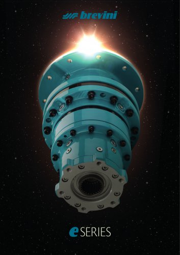 E Series
5 Pages
 CATALOGUE E series
274 Pages
- Electric gearmotor
- Planetary gearbox
- Coaxial gearhead
- Right angle gearhead
- Compact gearhead
- Solid-shaft gearhead
- Hollow-shaft gearhead
- Gear train gear reducer
- Gearbox for industrial applications
- Transmission gearhead
- Multi-stage gearhead
- Single-stage gearhead
- AC gear-motor
- Right angle electric gearmotor
- Coaxial gearmotor
- Shaft gearhead
- Solid-shaft gear-motor
- Helical gear gearhead
- Dual-stage gearbox