


- Products
- Catalogs
- News & Trends
- Exhibitions
K series

K series
K Series gearboxes are helical-bevel geared monoblock housing gearboxes designed for high efficiency and strength. They feature perpendicular input and output shafts and offer flexible connection options, including IEC B5 or B14 connections. Small sizes are available in 2 and 3 stages, while larger sizes are 3-stage types. They can be configured for high reduction operations up to 6 stages using double housings.
- High technology use
- Reliability
- High power density
- High efficiency
- Compatible mounting
- Flexible solutions
- Drawings are illustrative and not binding.
- Product changes can occur without notice.
- Operating instructions must be followed before commissioning.
- Oil quantities are guides; check with oil level plugs.
- Incorrect mounting position voids warranty.
- Output Torque (M2): Calculated by multiplying motor output torque by transmission ratio and efficiency.
- Nominal Torque (Ma): The mechanical torque the gearbox can resist under fs=1 conditions.
- Nominal Power (Pe): The power the gearbox can resist under fs=1 condition, detailed in performance tables.
- Ratio (i): The ratio between output and input shaft speeds, ranging from 3.5 to 23500.
- Equivalent Power and Torque: Calculated for constant speed but variable conditions.
- Required Power (PM): Power needed to drive the system.
- Required Torque (T): Must be equal or less than the output torque for the selected gearbox.
- Permissible Axial and Radial Loads: Defined for output or input shafts.
- Service Factor (fs): A safety coefficient for different working conditions, fs=1 for uniform loads.
- Noise Level: Below permitted values as per VDI guidelines 2159.
- Determine the service factor (fs) based on operating conditions.
- Calculate the required output torque (M2) and speed for the driven machine.
- Calculate the required power at the gearbox output.
- Determine the radial load at the output shaft based on the connection type.
1. DC-Link and Inverter System: The system converts AC to DC using a rectifier, storing energy in capacitors to reduce voltage ripple and provide energy during short power interruptions. The DC voltage is then converted back to AC using Pulse Width Modulation (PWM) through Insulated Gate Bipolar Transistors (IGBTs). The output voltage is a series of square wave pulses, which, combined with motor winding inductance, results in a sinusoidal current.
2. DC Motors:
a. General Specifications: DC drive systems have become more feasible with advancements in electronic components, offering features like guided startup, torque and current monitoring, and overload protection.
b. Operating Principles: DC motors require a DC output converter and include various windings. Voltage and current are supplied via carbon brushes and a commutator, necessitating regular maintenance.
c. Types of DC Motors: Two main types based on winding configuration, affecting torque-speed characteristics.
d. Speed Control: Speed is adjusted by altering DC voltage, with speed dropping as load increases. Speed differences can be compensated by adjusting (I x R) in the converter.
3. Electromagnetic Brakes:
a. Brake Types:
- Without Cooling: Mounted on the motor's back cover, suitable for short cycles.
- Fan Cooled: Includes a fan for long operations in enclosed spaces.
- With Hand Release: Manually operable, useful in power failures or mechanical issues.
b. Working Voltages: Available in 230V AC or 400V AC, with DC coil voltage requiring rectifiers or transformers. Standard delivery is 230V with a half-wave rectifier.
Key Parameters and Recommendations:
- Ensure regular maintenance of DC motors due to wear on carbon brushes.
- Choose appropriate brake type based on operational duration and environment.
- For precise speed control in DC motors, consider using a tachogenerator for actual value measurement.
- Consult Brevini Power Transmission S.p.A. for special brake voltage requirements.
1. Brakes without Cooling: Suitable for short operation times, mounted at the end of the motor shaft.
2. Brakes with Cooling: Designed for long operation times and enclosed spaces, featuring a fan for constant ventilation.
3. Brakes with Lever Arm: Can be used with or without cooling, manually operated, ideal for situations with no power supply.
Operating Voltages:
Electromagnetic brakes can be ordered with 230V AC or 400V AC. The brake coils require DC voltage, necessitating rectifiers or transformers.
1. 230V Supply: Voltage is reduced using half-wave or full-wave rectifiers.
2. 400V Supply: Voltage is reduced using half-wave rectifiers.
3. 24V DC Brakes: Voltage is transformed and rectified to DC.
Connection Types:
1. Delayed Braking: Used for slow and sliding brake systems, preventing shock loadings.
2. Immediate/Fast Braking: Used when short braking times are needed, common in lifting operations.
Brake Selection:
To select a brake, consider total inertia, maximum motor speed, maximum braking time, static torque, and safety coefficient. The necessary braking torque is calculated based on load direction and motor rotation.
Thermal Capacity:
After calculations, check the brake's thermal capacity to ensure it is within limits. Adjust the air-gap periodically to maintain performance.
Selection Example:
For a motor speed of 1400 rpm and a required torque of 50 Nm, a 150 Nm brake is suitable, with a thermal capacity of 1302 Joules, below the 18000 Joule limit.
- Specifications: The document lists dimensions for various motor types, including measurements 'k', 'k1', 'n', and 'n1'. The 'k1' dimension is specifically for motors equipped with brakes.
- Terminal Box Positions: Positions are specified for different motor sizes (e.g., 71-80-90-100-112-132), with a note that 'x' indicates if the motor is lower than the foot mounting plane.
- Dimensional Tables: Multiple tables provide detailed measurements for different motor types and sizes, including 'k', 'k1', 'n', and 'n1' values. These tables are repeated for various motor configurations.
- Brake Motor Dimensions: The 'k1' dimension is crucial for motors with brakes, indicating specific adjustments needed for these configurations.
- Mounting Considerations: The 'x' value in tables indicates whether the motor is positioned below the foot mounting plane, which is important for installation and operational considerations.
- Dimension 'k1': This measurement is specifically for motors equipped with brakes.
- Terminal Box Positions: The document outlines the positions of terminal boxes for different motor sizes, indicating if the motor is lower than the foot mounting plane.
- k: General dimension for motor size.
- k1: Dimension for motors with brakes.
- n and n1: Additional dimensions related to motor size and configuration.
- All dimensions are provided in millimeters.
- There are specific notes on the applicability of certain dimensions, particularly 'k1' for motors with brakes.
- The document is structured to provide quick reference for engineers and technicians working with these motor types.
This document provides detailed dimensional specifications for various motor types, focusing on the dimensions relevant to motors with brakes. The tables include measurements such as 'k', 'k1', 'n/n1', and 'm1' for different motor configurations (e.g., B5, B14).
Key Specifications:
- Dimension 'k1': This dimension is specifically for motors equipped with brakes.
- Tapped Center Hole: All motors feature a tapped center hole according to DIN 332, sheet 2.
Motor Types and Dimensions:
- For motor types 63/B5, 71/B5, 71/B14, 80/B5, and 80/B14, dimensions are provided for 'k', 'k1', 'n/n1', and 'm1'.
- Additional motor types such as 90S/B5, 90S/B14, 90L/B5, 90L/B14, 100L/B5, 100L/B14, 112M/B5, 112M/B14, 132S/B5, 132S/B14, 132M/B5, 132M/B14, 160M/B5, 160L/B5, 180M/B5, and 180L/B5 are also detailed with similar dimensional data.
Terminal Box Positions:
- Positions for terminal boxes are indicated as Poz.1, Poz.2, Poz.3, and Poz.4 for various motor sizes.
Additional Notes:
- For motors lower than the foot mounting plane, a specific dimension 'x' is noted.
- Standard operations and additional specifications are provided for each motor type.
The document provides detailed dimensional specifications for various motor types, including measurements such as 'k', 'k1', 'n/n1', and 'm1'. The 'k1' dimension is specifically for motors equipped with brakes. The document references the DIN 332 standard for tapped center holes.
Terminal Box Positions:
Information on terminal box positions is provided, with positions labeled as Poz.1, Poz.2, Poz.3, and Poz.4 for motor types ranging from 100 to 180.
Performance Tables:
The performance tables for the K Series Gear Units include nominal torques, ratios, output speeds, permissible radial loads (both input and output), and weights. The tables also specify nominal power for a service factor of 1.0.
Key Data from Tables:
- Nominal torques and output speeds are provided for various gear unit types.
- Input speeds are listed in rpm, with corresponding output speeds and permissible radial loads.
- The tables include data for different motor types, such as KT002, KT003, KT102, KT103, KT202, and KT203.
Standards and Recommendations:
The document adheres to DIN 332 standards for certain specifications and provides recommendations for motor dimensions when brakes are involved.
Catalog excerpts

brew ini power iranunittion If SERIES New Edition 2016 brevinigearmotors BREVINI CEARMOTORS Bevel Helical Gearboxes
Open the catalog to page 1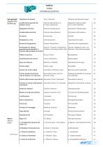
Indice Index Inhaltsverzeichnis Info generali General Info. Einfuhrung Motori Motors Motor Significato dei simboli Caratteristiche generali dei riduttori serie K Spiegazioni tecniche Caratteristiche tecniche Accessori Designazione unita Esempi di designazione Combinazioni di rapporti geometricamente possibili, in funzione della grandezza del motore Fattore di servizio Classificazione dei carichi Senso di rotazione Carichi radiali Calcolo dei carichi radiali Carichi assiali ammessi per i tipi di riduttore con estrusore Calcolo della potenza equivalente Esempio di calcolo della potenza equivalente Scelta...
Open the catalog to page 3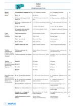
Indice Index Inhaltsverzeichnis Motori Motors Motor Freni Brakes Bremsen f- Convertitori di frequenza in CA Motori CC a- Caratteristiche generali dei motori CC b- Principi di funzionamento dei motori CC c- Tipi di motori CC d- Controllo della velocita di rotazione dei motori CC Freni elettromagnetici Tipi di freni Tipi di connessione Scelta dei freni Capacita termica dei freni f- AC Frequency Inverters DC Motors a- DC Motors general specifications b- DC Motors operating principles c- Types of DC Motors d- DC motors Speed Control Electromagnetic Brakes Brake Types Connection Types Brake Selection Brake...
Open the catalog to page 4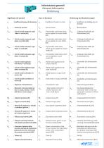
Informazioni generali General Information Einfuhrung qa alberi in entrata [N] F : Carichi radiali sull'albero in ext lato di uscita, ridotto a livello dell'albero motore [kgm2] macchina azionata dal riduttore (per potenze diverse fare riferimento alla potenza equivalente) [kW] input shafts [N] Fq ; Radial loads on output shaft J ; Total outside moment of ext inertia reduced to the motor shaft [kgm2] rotierende Teile von der Aus gangsseite reduziert auf Motor welle [kgm2]
Open the catalog to page 5
Informazioni generali General Information Einführung Note / Notes / Notizen
Open the catalog to page 6
Informazioni generali General Information Einführung Note / Notes / Notizen
Open the catalog to page 7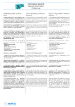
Informazioni generali General Information Einführung Caratteristiche generali dei riduttori serie K General Specifications of K Series Gearboxes Allgemeine Eigenschaften von K Serie Getrieben I riduttori della serie K sono riduttori ad assi ortogonali monoblocco. Sono progettati per applicazioni che richiedono un più alto rendimento e maggiore resistenza. L'albero in entrata e quello in uscita sono perpendicolari tra loro. K Series gearboxes are helical-bevel geared monoblock housing gearboxes. K Series are designed for higher efficiency and higher strength required operations. Input and output...
Open the catalog to page 8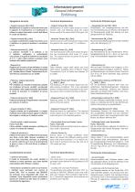
Informazioni generali General Information Einführung Spiegazioni tecniche Technical Explanations Technische Erläuterungen - Coppia trasmessa (M2): [Nm] Moltiplicando la coppia in uscita dal motore per il rapporto di trasmissione e il rendimento si ottiene la coppia trasmessa a livello dell'albero in uscita dal riduttore. - Output Torque (M2): [Nm] Multiplication of motor output torque by transmission ratio and efficiency gives the output torque result at the output shaft of the gear unit. - Ausgangsmoment (M2): [Nm] Multiplikation von Ausgangsmoment des Motors mit Übersetzung und Division das...
Open the catalog to page 9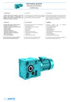
Informazioni generali General Information Einfuhrung - Lubrificazione: I riduttori della serie K utilizzano i tipi di olio riportati nelle tabelle di lubrificazione. Per maggiori informazioni sulla lubrificazione, fare riferimento alla sezione dedicata. - Lubrication: K series gearboxes are filled with oils indicated on the lubrication tables. For lubrication details please refer to the lubrication section. - Schmierung: K Serie Getriebe werden mit Olen entsprechend der Schmierungstabellen, falls nicht anders ver-einbart, geliefert. Fur weitere Schmierungsan-gaben siehe Kapitel Schmierung. -...
Open the catalog to page 10
Informazioni generali General Information Einführung
Open the catalog to page 11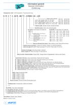
Informazioni generali General Information Einführung Designazione unità / Unit Designation / Typenbezeichnung K R 3 7 3 . 02 R - M2 T1 - 3 E90S / 4C - L05 Freno / Brake / Bremse L-220 V Con ventola / With Fan / Mit Lüfter P-24 V Con ventola / With Fan / Mit Lüfter S-220 V Senza ventola / Without Fan / Ohne Lüfter Z-24 V Senza ventola / Without Fan / Ohne Lüfter Numero di poli / Number of poles / Anzahl der Polen Grandezza motore / Motor Size / Motorbaugröße Per tipi KV / For KV types / Für typen KV E90 S / 4 Numero di poli / Pole Number / Anzahl der polen Lunghezza corpo / Frame Length / Gehäuselänge...
Open the catalog to page 12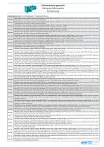
Informazioni generali General Information EinfuhrungDesignazione unita / Unit Designation /Typenbezeichnung KR..00..
Open the catalog to page 13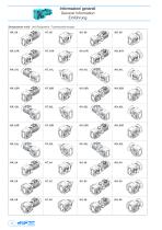
Informazioni generali General Information Einführung Designazione unità / Unit Designation / Typenbezeichnungen KR..00
Open the catalog to page 14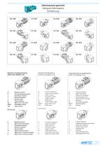
Informazioni generali General Information Einfuhrung KR..0SR Esempi di designazioneKR273.00-3E90S/4-L05TypenbezeichnungsbeispieleKR273.00-3E90S/4-L05 K : Riduttore serie K 00 : Albero cavo all’uscita T : Albero pieno all’entrata 01 : Albero pieno all’uscita L : Albero cavo in uscita a sinistra R : Albero cavo in uscita a destra
Open the catalog to page 15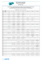
Informazioni generali General Information Einfuhrung Combinazioni di rapporti geometricamente possibili, in funzione della grandezza del motore Geometrically Possible Ratios Combinations According to Motor Size Geometrisch mogliche Kombinationen von Ubersetzungen nach MotorbaugroUe
Open the catalog to page 16
Informazioni generali General Information Einfuhrung Combinazioni di rapporti geometricamente possibili, in funzione della grandezza del motore Geometrically Possible Ratios Combinations According to Motor Size Geometrisch mogliche Kombinationen von Ubersetzungen nach MotorbaugroUe
Open the catalog to page 17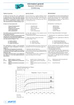
Informazioni generali General Information Einfuhrung Fattore di servizio Il fattore di servizio (fs) e un coefficiente di sicurezza che tiene conto delle diverse condizioni di lavoro della macchina azionata dal riduttore. In presenza di carichi uniformi per 8 ore di funzionamento al giorno e fino a 100 avviamenti all'ora si utilizza il fattore "fs=1". Il fattore di servizio dipende da: - Tempo di funzionamento - Natura del carico - Frequenza di avviamento - Tipo di azionamento - Altre considerazioni Per stabilire quale sia il giusto fattore di servizio per la propria macchina: 2. Selezionare...
Open the catalog to page 18All Brevini Power Transmission catalogs and technical brochures
 S series
164 Pages
 Slewing drives
112 Pages
 BGM
BGM18 Pages
 S6CV
S6CV64 Pages
 MEDIUM PRESSURE MOTORS AND PUMPS
124 Pages
 series 498
2 Pages
 series 492
2 Pages
 series 392/393
2 Pages
 SH11C
SH11C24 Pages
 H1C
H1C18 Pages
 INDUSTRIAL SERIES
260 Pages
 LEONESSA BREVINI
57 Pages
 Hand pumps
40 Pages
 Valves and Electronics
274 Pages
 VPS Mobile Valves
68 Pages
 MC Tubes kit / Kit tub
38 Pages
 MC Hydraulic power pack
64 Pages
 FP Hydraulic power pack
100 Pages
 MB Orbital geared motors
20 Pages
 Low speed high torque Orbital Motors
192 Pages
 Axial piston Pumps and Motors
530 Pages
 Rotary Drilling
5 Pages
 Bulk Mining Industrail
11 Pages
 Deck Crane Brochure
5 Pages
 Off-highway Product Range
13 Pages
 Hoisting and Recovery Winches
125 Pages
 MOBILE SLEWING DRIVES
106 Pages
 SU IM SERIES
40 Pages
 ML B RD SERIES
48 Pages
 MR
MR4 Pages
 MP
MP1 Page
 MC
MC38 Pages
 MB
MB20 Pages
 BFP
BFP4 Pages
 M series
408 Pages
 V series
224 Pages
 Hoisting&Recovery Winches
115 Pages
 WINCH DRIVES
16 Pages
 INDUSTRIAL PLANETARY GEARBOXES
260 Pages
 ASu Series
3 Pages
 ASu66 Series
3 Pages
 SP MkII Series
2 Pages
 TAC MkII Series
2 Pages
 TLu Series
2 Pages
 TLu66 series
2 Pages
 VT Series
8 Pages
 MC4 Series
8 Pages
 MC2 Series
8 Pages
 Powerpacks
4 Pages
 FP Series
80 Pages
 Take Up Winches for mining
16 Pages
 S Series Big
20 Pages
 Marine Technologies
14 Pages
 Winches overview
16 Pages
 Sugar mill drives
22 Pages
 Hydraulic Cylinders
2 Pages
 OT Silent Plus Pumps
10 Pages
 OT 300 Group 3 pumps
68 Pages
 OT 200 Group 2 pumps
127 Pages
 OT 100 Group 1 pumps
84 Pages
 S6CV Pumps
68 Pages
 SH11C Pumps
20 Pages
 SH5AV Pumps
28 Pages
 MD10V Pumps
99 Pages
 BRZ Orbital Motors
10 Pages
 HT Orbital Motors
19 Pages
 HR Orbital Motors
27 Pages
 AR - ARS Orbital Motors
22 Pages
 BR-BS Orbital Motors
30 Pages
 BGM Orbital Motors
19 Pages
 BG-BH Orbital Motors
31 Pages
 SH7VR Series
49 Pages
 SH7V Series
74 Pages
 MD11V Series
13 Pages
 SH11CR Series
16 Pages
 SH11C Series
24 Pages
 Twin Screw Extruder Drives
12 Pages
 Planetary Bevel Helical Posiplan
125 Pages
 S-Series Planetary Gearboxes
162 Pages
 Industrial Planetary Gearboxes
260 Pages
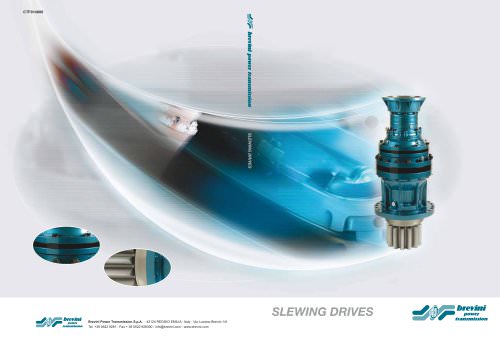 Yaw and Pitch Drives
106 Pages
 Planetary wheel drives
129 Pages
 Helical & Bevel helical Gearboxes
171 Pages
 Lifting / Hoisting Gearboxes
37 Pages
 Long Travel Drives
12 Pages
 Conveyor Drives
12 Pages
 Single Screw Extruder Drives
115 Pages
 Injection Molding Drives
12 Pages
 Recovery winches
115 Pages
 Winch drives
108 Pages
 Atex Gearboxes Catalogue
30 Pages
 Slewing drives
110 Pages
 S-Series
160 Pages
 Catalog
250 Pages



Archived catalogs
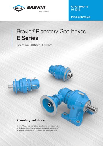 E series_2019
272 Pages
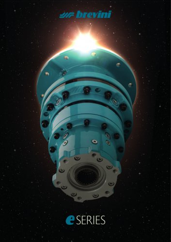 E Series
5 Pages
 CATALOGUE E series
274 Pages
- Electric gearmotor
- Planetary gearbox
- Coaxial gearhead
- Right angle gearhead
- Compact gearhead
- Solid-shaft gearhead
- Hollow-shaft gearhead
- Winch
- Gear train gear reducer
- Gearbox for industrial applications
- Transmission gearhead
- Multi-stage gearhead
- Single-stage gearhead
- AC gear-motor
- Right angle electric gearmotor
- Coaxial gearmotor
- Shaft gearhead
- Solid-shaft gear-motor
- Helical gear gearhead
- Dual-stage gearbox