- Catalogs
- Brevini Power Transmission
- FP Series
- Products
- Catalogs
- News & Trends
- Exhibitions
FP Series
1 /80Pages

FP Series
1 /80Pages
Catalog excerpts

FP HYDRAULIC POWER PACK Technical Catalogue April
Open the catalog to page 1
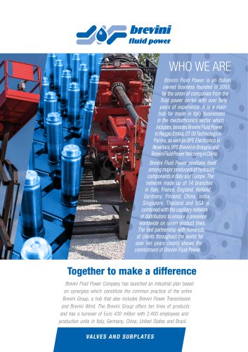
Brevini Fluid Power, part of the Brevini group, was established in 2003 in Reggio Emilia where it has its head office. Brevini Fluid Power manufactures hydraulic components and application packages: a very large range suited to several operational requirements and applications thanks to a strict interaction between mechanical, hydraulic and electronic components. Brevini Fluid Power is among the top manufacturers in Italy and a major player in Europe and in the world. International presence Brevini Fluid Power operates internationally with 15 branches all over the world placed in major industrialized...
Open the catalog to page 2
© 2016 Brevini Fluid Power S.p.A. All rights reserved. Hydr-App, SAM Hydraulik, Aron, Brevini Hydraulics, BPE Electronics, VPS Brevini, OT Oiltechnology, logos are trademarks or are registered trademarks of Brevini Fluid Power S.p.A. or other companies of the Brevini Group in Italy and other countries. The technical features supplied in this catalogue are non binding and no legal action can be taken against such material. Brevini Fluid Power will not be held responsible for information and specifications which may lead to error or incorrect interpretations. Given the continuous technical research...
Open the catalog to page 3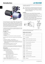
Introduction The validation of the endhead follows a life-test with 250 bar pulsed pressure repeated for 100.000 cycles Operating pressure is controlled by the maximum pressure valve and the type of pump used (in terms of performance) may be determined by the maximum pressure valve. Therefore, it is essential not to change the maximum pressure valve. If neccessary, contact our technical service department Installation 1) The power pack must be mounted using the M10 holes on the endhead. 2) The power pack must not come into contact with sheet metal, protective guards or any parts that may vibrate...
Open the catalog to page 4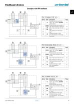
Endhead choice Examples with FPA endhead A Description Pressure relief valve with check valve ( > 60 ÷ 180 bar), standard B setting 150 bar Piloted solenoid valve normally clo2DAAA sed, without emergency. Voltage 12 +B VDC + Flow control valve 1.4 l/min 5TG Plug Not specified, drain lines 6 and 7 open Combinations plugs on ports -03 (A= with protection; B= with plug) End section - Description Pressure relief valve with check B(170) valve ( > 60 ÷ 180 bar), special setting 170 bar Piloted solenoid valve normally 2DAAA closed, without emergency. Voltage 12 VDC 5TG Plug + Flow control valve 1.4...
Open the catalog to page 5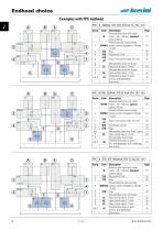
Endhead choice Examples with FPC endhead Description Pressure relief valve with check 1 B(170) valve ( > 60 ÷ 180 bar), special setting 170 bar Piloted solenoid valve normally 2 2DAAA closed, without emergency. Voltage 12 VDC 3TG 3 Plug + Flow control valve 1.4 l/min +B 4 4HA Push-button control 5 5TH Plug Not specified, drain lines 6 and 7 open 6-7 8 Flow control valve 2.1 l/min 8C Not specified, drain 9 open 9 Combinations plugs on ports A-B-C -05 (A = with protection; B-C= with plug) End section - Description Pressure relief valve with check 1 valve ( > 60 ÷ 180 bar), standard B setting 150...
Open the catalog to page 6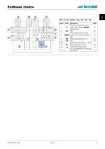
Description Page Pressure relief valve with check 1 valve ( > 60 ÷ 180 bar), standard 23 B setting 150 bar 2 26 2TC Plug Piloted solenoid valve normally 3 28 3DDAA closed, with emergency. Voltage 12 VDC 4 32 4ZA Hand pump displacement 1cc 5 33 5TH Plug 6-7-8 Not specified, drain lines 6 - 7 - 8 open 9 Flow control valve 2.1 l/min 34 9C Combinations plugs on ports A-B-C 35 -05 (A = with protection; B-C= with plug) End section — -
Open the catalog to page 7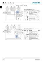
Endhead choice Examples with FPE endhead Description Page Pressure relief valve with check valve ( > 60 ÷ 180 bar), standard 36 B setting 150 bar Directional control valve 4 way 3 38 2D(1A)AA positions with emergency. Voltage 12 Vdc (closed centre “C” spool) 3TC Plug + Flow control valve 1.4 l/min 40 +B Not specified, drain 9 open — — Combinations plugs on ports 42 -04 (A-B= with protection; C-D= with plug) End section — - Description Page Pressure relief valve with check valve ( > 60 ÷ 180 bar), standard 36 B setting 150 bar Directional control valve 4 way 2 po38 2D(2A)AA sitions without emergency....
Open the catalog to page 8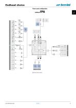
Endhead choice Power pack configuration endhead Flow control valves
Open the catalog to page 9
Endhead choice Power pack configuration Flow control valves (or plug for cavity 9) 4FA
Open the catalog to page 10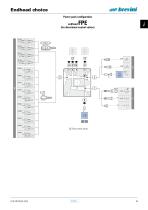
Endhead choice Power pack configuration (for directional control valves) Flow control valves
Open the catalog to page 11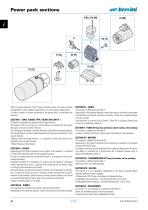
Power pack sections VIII (J-K-W) With its great modularity, the FP series of power packs can create multiple configurations which satisfy requirements in a wide range of applications. To make it easier to choose components, the power pack is subdivided into sections. SECTION I - SERIE, FLANGE TYPE, VALVES ON CAVITY 1 FP Series Powerpacks are based on the Flange features. The Flange is the core of the unit, on the flange are mounted all the valves, the pump, the motor and the reservoir. The FP Flange is available in several Versions (with different tooling options). The Flange Version must be...
Open the catalog to page 12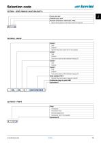
Selection code SECTION I - SERIE, ENDHEAD, VALVES ON CAVITY 1 Power pack type Endhead power pack Pressure relief valve - Check valve - Plug Special setting pressure relief valve (omit if not required) FP * * (...) SECTION II - VALVES Cavity 2 Type Features Optional flow control valve (omit if not required) Cavity 3 Type Features Flow control valve can be combined with plug TC Cavity 4 Type Features Cavity 5 Plug Features Flow control valve can be combined with plug TG Drain cavities 6-7-8-9 Optional flow control valve (or plug for cavity 9) Combination plugs for ports (ABC) End section II SECTION...
Open the catalog to page 13
Selection code SECTION IV - TANKS / SECTION V - TUBES KIT Section: S = tank (with tubes kit) ; G = only with tubes kit, without tank; OMIT if without tank and without tubes kit Capacity liters Features (material and construction) Mounting position: H = horizontal; V = vertical Variants 00 = standard, no variant; OMIT if with tubes kit (section “G”) Orientation OMIT if with tubes kit in vertical mounting position (section “G”) End section IV and V * ** * (*) ** SECTION VI - MOTORS DC motor Voltage Power / Size Version Accessories 0 = whitout accessories; Orientation End section VI M * ** (*) *...
Open the catalog to page 14All Brevini Power Transmission catalogs and technical brochures
 S series
164 Pages
 Slewing drives
112 Pages
 BGM
BGM18 Pages
 S6CV
S6CV64 Pages
 MEDIUM PRESSURE MOTORS AND PUMPS
124 Pages
 series 498
2 Pages
 series 492
2 Pages
 series 392/393
2 Pages
 SH11C
SH11C24 Pages
 H1C
H1C18 Pages
 INDUSTRIAL SERIES
260 Pages
 LEONESSA BREVINI
57 Pages
 Hand pumps
40 Pages
 Valves and Electronics
274 Pages
 VPS Mobile Valves
68 Pages
 MC Tubes kit / Kit tub
38 Pages
 MC Hydraulic power pack
64 Pages
 FP Hydraulic power pack
100 Pages
 MB Orbital geared motors
20 Pages
 Low speed high torque Orbital Motors
192 Pages
 Axial piston Pumps and Motors
530 Pages
 Rotary Drilling
5 Pages
 Bulk Mining Industrail
11 Pages
 Deck Crane Brochure
5 Pages
 Off-highway Product Range
13 Pages
 Hoisting and Recovery Winches
125 Pages
 MOBILE SLEWING DRIVES
106 Pages
 SU IM SERIES
40 Pages
 ML B RD SERIES
48 Pages
 MR
MR4 Pages
 MP
MP1 Page
 MC
MC38 Pages
 MB
MB20 Pages
 BFP
BFP4 Pages
 M series
408 Pages
 K series
488 Pages
 V series
224 Pages
 Hoisting&Recovery Winches
115 Pages
 WINCH DRIVES
16 Pages
 INDUSTRIAL PLANETARY GEARBOXES
260 Pages
 ASu Series
3 Pages
 ASu66 Series
3 Pages
 SP MkII Series
2 Pages
 TAC MkII Series
2 Pages
 TLu Series
2 Pages
 TLu66 series
2 Pages
 VT Series
8 Pages
 MC4 Series
8 Pages
 MC2 Series
8 Pages
 Powerpacks
4 Pages
 Take Up Winches for mining
16 Pages
 S Series Big
20 Pages
 Marine Technologies
14 Pages
 Winches overview
16 Pages
 Sugar mill drives
22 Pages
 Hydraulic Cylinders
2 Pages
 OT Silent Plus Pumps
10 Pages
 OT 300 Group 3 pumps
68 Pages
 OT 200 Group 2 pumps
127 Pages
 OT 100 Group 1 pumps
84 Pages
 S6CV Pumps
68 Pages
 SH11C Pumps
20 Pages
 SH5AV Pumps
28 Pages
 MD10V Pumps
99 Pages
 BRZ Orbital Motors
10 Pages
 HT Orbital Motors
19 Pages
 HR Orbital Motors
27 Pages
 AR - ARS Orbital Motors
22 Pages
 BR-BS Orbital Motors
30 Pages
 BGM Orbital Motors
19 Pages
 BG-BH Orbital Motors
31 Pages
 SH7VR Series
49 Pages
 SH7V Series
74 Pages
 MD11V Series
13 Pages
 SH11CR Series
16 Pages
 SH11C Series
24 Pages
 Twin Screw Extruder Drives
12 Pages
 Planetary Bevel Helical Posiplan
125 Pages
 S-Series Planetary Gearboxes
162 Pages
 Industrial Planetary Gearboxes
260 Pages
 Yaw and Pitch Drives
106 Pages
 Planetary wheel drives
129 Pages
 Helical & Bevel helical Gearboxes
171 Pages
 Lifting / Hoisting Gearboxes
37 Pages
 Long Travel Drives
12 Pages
 Conveyor Drives
12 Pages
 Single Screw Extruder Drives
115 Pages
 Injection Molding Drives
12 Pages
 Recovery winches
115 Pages
 Winch drives
108 Pages
 Atex Gearboxes Catalogue
30 Pages
 Slewing drives
110 Pages
 S-Series
160 Pages
 Catalog
250 Pages


Archived catalogs
 E series_2019
272 Pages
 E Series
5 Pages
 CATALOGUE E series
274 Pages
- Electric gearmotor
- Planetary gearbox
- Coaxial gearhead
- Right angle gearhead
- Compact gearhead
- Solid-shaft gearhead
- Winch
- Gear train gear reducer
- Hollow-shaft gearhead
- Gearbox for industrial applications
- Transmission gearhead
- Right angle electric gearmotor
- Multi-stage gearhead
- Shaft gearhead
- Single-stage gearhead
- Coaxial gearmotor
- AC gear-motor
- Helical gear gearhead
- Solid-shaft gear-motor
- Gear train gearmotor