
- Catalogs
- Brevini Power Transmission
- E series_2019


- Products
- Catalogs
- News & Trends
- Exhibitions
E series_2019
E series_2019
- Thermal Factor (fK): Adjusts PT for intermittent use and ambient temperatures different from 20°C.
- Speed Factor (fV): Adjusts PT for input speeds different from 1,500 rpm, considering different mounting positions.
- Environmental Factor (fR): Adjusts PT for gear units located in confined spaces or outdoors.
- Input Power (P1): The power applied at the input, calculated using the required output torque and output speed.
- Output Power (P2): The power transmitted at the output, calculated using the dynamic efficiency of the gear unit.
- Ensure that the applied power (P1) is always less than the corrected thermal power (PT1) as per formula (8). If PT1 is less than the power to be transmitted at any point, an auxiliary cooling circuit is required. Consult the DANA contact for circuit selection.
- If an input brake is selected, verify that the calculated output braking torque is less than the maximum transmissible output torque (T2MAX).
- Choose the appropriate motor type (orbital, gear, radial piston, axial piston, cam) based on application type and operating pressure.
- Calculate the required input torque (T1R) and theoretical displacement (VR) for the hydraulic motor using provided formulas.
- For electric motors, calculate input power (P1) and ensure it satisfies the nominal power (Pn) requirements, considering duty cycles S2 and S3 for potential power increases.
- Application: Conveyor not uniformly fed.
- Required output torque (T2R): 5,500 Nm; Max output torque (T2RMAX): 10,000 Nm.
- Input speed (n1): 1,500 rpm; Output speed (n2): 12 rpm.
- Required radial load on output shaft (FrR2): 40,000 N.
- Calculate lifetime factor (Lh2) and reduction ratio (i) using provided formulas.
- Select gear unit with characteristics satisfying equations (15) and (16) and a reduction ratio close to i = 125.
- Use tables to determine nature of load, duty factor (fs), and gear unit size.
- Ensure gear unit nominal torque (T2N) is immediately higher than calculated T2R x fs.
- Prohibition of unauthorized modifications to the gear unit and accessories.
- Use of appropriate lifting equipment to avoid impacts on shaft ends.
- Prohibition of welding on gear units.
- Ensuring the gear unit is stopped during installation or maintenance to prevent accidental activation.
- Use of the DANA E00 Universal adapter system for motors up to 100 kg and 1,000 Nm torque, with specific adapters for heavier motors.
- Provision of adequate accident-prevention devices for connections involving rotating parts.
- Ensure the shaft and its seat are clean and free of grease. Use a suitable bearing to center the shaft for easier disassembly later.
- Lubricate the coupling seat with molybdenum disulfide grease. New couplings do not require disassembly for lubrication.
- Mount the coupling to the gearbox without tightening the screws. Ensure the coupling is secure, especially in vertical installations with the shaft facing downward.
- Fit the shaft into its seat without interference, ensuring precise alignment using lifting equipment. Avoid applying axial forces that could damage bearings.
- Position the coupling against the shaft shoulder before tightening screws.
- Tighten screws in a circular sequence using a torque wrench, initially set to the specified torque, then increase by 3-5% for final tightening. Ensure no further tightening is possible.
- Protect the coupling area with a sheet casing if there is a risk of debris.
- Loosen screws gradually until the coupling can move on the hub. Do not fully remove screws until rings separate naturally to avoid violent disassembly.
- If rings do not separate, use screws in extraction holes to separate the inner and outer rings.
- Use appropriate equipment to support and separate the gear unit from the machine shaft. If necessary, use hydraulic pushers.
- For long-term disassembly, clean and lubricate all surfaces before reassembly.
- The torque arm must allow axial movement and have sufficient play to accommodate small oscillations without overloading the gear unit.
- Use long-life ball joints with PTFE protection or steel-to-steel joints with periodic greasing.
- The anchorage rod should be parallel to the torque arm to ensure side clearance for free movement.
- The fixed support must provide adequate anchorage for the load.
- Avoid any welding work involving the gear unit.
- Always use a torque wrench for tightening connection screws.
- The torque arm must move freely in the axial direction and have sufficient play to accommodate minor fluctuations without overloading the gearbox. Use ball joints for optimal performance.
- Durable ball joints with PTFE-protected friction surfaces are recommended. Alternatively, steel-on-steel joints can be used but require regular lubrication.
- The connecting rod should be parallel to the torque arm to ensure lateral play and structural movement freedom.
- The fixed end of the connecting rod must ensure proper load anchoring.
- Avoid welding on the gearbox, even for grounding purposes.
- Always use a torque wrench to tighten screws.
- The torque arm must be perfectly straight.
- Welded parts should be sanded, normalized, and corrected for deformations.
- The contact area of the torque arm at the gearbox flange must be perfectly flat.
- Remove all grease traces from contact surfaces before connecting the torque arm to the gearbox.
- The correct configuration depends on the gearbox rotation direction. The connecting rod should be in traction, not compression. If necessary, mount the torque arm on the opposite side shown in Fig. 23.
- In shaft mounting assemblies, consider the weights of the gearbox, torque arm, and connected elements, as they create loads and tipping moments supported by the output bearings. Minimize the weight of components connected to the gearbox and decentralize non-essential elements.
- DANA gear units are supplied without lubricant; users must fill them correctly before starting the machine.
- Important oil parameters include viscosity at nominal operating conditions and additives.
- Nominal viscosity is referenced at 40°C and decreases with temperature increase. For operating temperatures between 50°C and 70°C, choose the highest viscosity if high temperatures are expected.
- Use high viscosity oils with Extreme Pressure (EP) additives for heavily loaded and low-speed output stages.
- Use oils with EP and antiwear properties according to ISO 6743-6 L-CKC or DIN 51517-3 CLP standards.
- Mineral oils, Polyalphaolefin (PAO) synthetic oils, and Polyalkylene glycol (PAG) synthetic oils are available.
- Mineral oils are suitable for gear units with discontinuous cycles and no significant temperature changes.
- Use PAO synthetic oils for heavily loaded gear units with continuous operation and temperature increases.
- PAG oils are not recommended due to incompatibility with other oils and potential chemical activity against seals and internal paints.
- Metal microparticles can contaminate oil during normal operation, reducing bearing life and causing premature gearbox failure.
- Use an auxiliary circulation system with filtration and cooling to control contamination and stabilize operating temperature.
Catalog excerpts
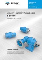
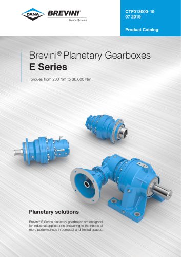
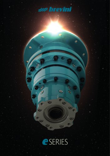
Brevini® Planetary Gearboxes E Series Torques from 230 Nm to 36.600 Nm Planetary solutions Brevini® E Series planetary gearboxes are designed for industrial applications answering to the needs of more performances in compact and limited spaces.
Open the catalog to page 1
BREVINT Motion Systems
Open the catalog to page 3
Eccellenza tecnologica, Efficienza meccanica, Economie di esercizio e funzionamento, Esperienza industriale DANA. Questi sono i pregi della nuova Serie E: la soluzione ideale per l’industria del terzo millennio. Technological Excellence, Mechanical Efficiency, Operating Economies, DANA industrial Expertise. These are the qualities of the new E Series: the ideal solution for industry in the third millennium. Infatti questa innovativa serie di riduttori epicicloidali, perfetta per applicazioni industriali con coppie e potenze intermedie, è la risposta DANA alle esigenze di clienti globalizzati,...
Open the catalog to page 5
Integrazione con la Serie S DANA per applicazioni “heavy duty” e cicli di lavoro gravosi. Integration with the DANA S Series for “heavy duty” applications and heavy work cycles. Integrierung in die Serie S von DANA für „Heavy-Duty-Anwendungen“ und bei erschwerten Arbeitszyklen. Tempi di consegna veloci, grazie a razionali processi manifatturieri e di logistica industriale. Prompt delivery times, thenks to rational manufacturing processes and industrial logistics. Kurze Lieferzeiten, dank rationeller Fertigungsprozesse und industrieller Logistik. In dettaglio, la Serie E è articolata su 9 grandezze...
Open the catalog to page 6
Energie rinnovabili / Green Energy / Erneuerbare Energie Settore Minerario / Mining Quarrying / Bergbau Gewinnung Applicazioni Speciali / Custom Applications / Individuelle Anwendungen Impianti Industriali / Industrial Equipment / Industrieanlagen Industria Alimentare / Food and Beverage / Lebensmittelindustrie A
Open the catalog to page 7
BREVINIMotion Systems Questa pagina e lasciata intenzionalmente bianca Page is intentionally left blank Seite wurde absichtlich leer gelassen
Open the catalog to page 8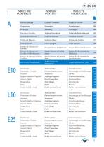
INDICE DEI INDEX OF INHALTS-CONTENUTI CONTENT VERZEICHNIS Riduttori SERIE E E SERIES Gearboxes E SERIES Getriebe Designazione Designation Bezeichnungen Simbologia Descrizioni Tecniche Selezione del Riduttore Verifica del Riduttore Scelta del Motore Esempio di Selezione del Riduttore Esempio di Selezione del Circuito di Raffreddamento Esempio di Selezione del Freno Lamellare Symbology Technical Description Gear Unit Selection Gearboxes Check Choice of Engine Example of Gear Unit Selection Sample Selection of Cooling System Sample Selection of Lamellar Brake Symbologie Technische Beschreibungen...
Open the catalog to page 9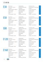
Dati Tecnici Dati Tecnici Dati Tecnici Dati Tecnici Dati Tecnici
Open the catalog to page 10
Uscite Output Abtriebe .01 Supporti Maschio in Ingresso Input Male Shaft Antriebswellenstumpfe .08 Freni lamellari a bagno dolio Multidisc Brake in oil Lamellenbremsen in Olbad .09 Entrate universali Universal Inputs Universal Antriebe .11 Flange motori SAE J 744C Motor Flanges SAE J 744C Motorflansche SAE J 744C .12 Flange motori NEMA Motor Flanges NEMA Motorflansche NEMA .13 Stato di fornitura Supply Condition Lieferbendingungen .14 Condizioni di stoccaggio Storing Condition Langerbendingungen .14 Installazione Installation Installation .15 Giunto ad attrito Shrink Disc Reibungskupplung .18...
Open the catalog to page 11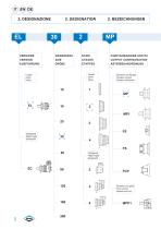
VERSIONE VERSION AUSFUHRUNG GRANDEZZA STADI SIZE STAGES GROBE ETAPPES CONFIGURAZIONE USCITA OUTPUT CONFIGURATION ABTRIEBSANORDNUNG Lineari Inline Inline Lineari Versione con flangia Inline Flanged version Inline Version mit flansch Versione con piedi Foot version Version mit FuR
Open the catalog to page 14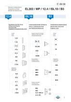
Esempio di designazione: Designation example: IP / 12.4 / ISL10 / B3 ISL10 RAPPORTO EFFETTIVO EFFECTIVE RATIO EFFEKTIVES UBERSETZUNGSVERHALTNIS CONFIGURAZIONE ENTRATA INPUT CONFIGURATION ANTRIEBSANORDNUNG POSIZIONI DI MONTAGGIO MOUNTING POSITION EINBAULAGE Lineari Inline Inline Supporti maschio in entrata Lineari Cylindrical male input shaft Inline Antriebswellenstumpfe Inline Freni lamellari Multidisc brakes Lamellenbremsen Ortogonali Right angle Senkrecht Ortogonali Right angle Senkrecht Entrata universale Universal input Universalantriebe
Open the catalog to page 15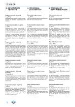
Coppia nominale in uscita T2n [Nm] Rappresenta la coppia in uscita conven-zionale che identifica la grandezza del riduttore. Nominale output torque T2N [Nm] The conventional output torque thet identifies the size of the gear unit. Abtriebsnennmoment T2n [Nm] Ist das konventionelle Abtriebsmomentals Kennezichnung der GroUe. Coppia trasmissibile in uscita T2 [Nm] Rappresenta la coppia trasmissibile in uscita dal riduttore con carico continuo e uniforme (fattore di servizio fs=1), per diversi valori del fattore di durata n2xh. I valori di T2 sono calcolati secondo gli standard ISO 6336 per gli ingranaggi...
Open the catalog to page 18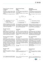
Coppia frenante richiesta in ingresso Tbr [Nm] Rappresenta la coppia frenante richiesta in ingresso al riduttore qualora l'appli-cazione preveda I'utilizzo di un freno in ingresso. E' calcolabile con la seguente relazione: Required input braking torque tbr [Nm] The required gear unit input braking torque if the application involves the use of an input brake. It can be calculated with the following equation: Gefordertes Antriebsbremsmoment Tbr [Nm] 1st das geforderte Antriebsbremsmoment fur das Getriebe, wenn die Anwendung den Einsatz einer Antriebsbremse for-dert. Kann mit folgender Formel berechnet...
Open the catalog to page 19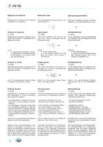
Rapporto di riduzione i Rappresenta la relazione fra la velocita in ingresso n-i ed uscita n2. Reduction ratio i The ratio between the input speed n1 and output speed n2. Ubersetzungsverhaltnis i Stellt das Verhaltnis zwischen Antriebs-drehzahl n1 und Abtriebsdrehzahl n2 dar. Potenza in ingresso P1 [kW] Rappresenta la potenza applicata all'in-gresso del riduttore. E' calcolabile con la seguente formula: Input power P1 [kW] The power applied at the input of the gear unit. It can be calculated with the following formula: (3) Antriebsleistung P1 [kW] Ist die angelegte Leistung antriebsseitig vom...
Open the catalog to page 20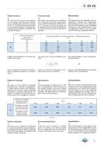
Fattore termico fK Nel caso di cicli di lavoro che prevedo-no un impiego intermittente del riduttore e/o una temperatura ambiente diversa da 20 °C, la potenza termica del riduttore puo essere adeguata all'applicazione specifica tramite il fattore fK riportato nel-la tabella seguente. Thermal factor fK With work cycles requiring an intermittent use of the gear unit and/or the presence of an ambient temperature different from 20 °C, the gear unit thermal rating can be adjusted to the specific application by means of the factor fK given in the following table. Warmefaktor fK Bei Arbeitszyklen des...
Open the catalog to page 21All Brevini Power Transmission catalogs and technical brochures
 S series
164 Pages
 Slewing drives
112 Pages
 BGM
BGM18 Pages
 S6CV
S6CV64 Pages
 MEDIUM PRESSURE MOTORS AND PUMPS
124 Pages
 series 498
2 Pages
 series 492
2 Pages
 series 392/393
2 Pages
 SH11C
SH11C24 Pages
 H1C
H1C18 Pages
 INDUSTRIAL SERIES
260 Pages
 LEONESSA BREVINI
57 Pages
 Hand pumps
40 Pages
 Valves and Electronics
274 Pages
 VPS Mobile Valves
68 Pages
 MC Tubes kit / Kit tub
38 Pages
 MC Hydraulic power pack
64 Pages
 FP Hydraulic power pack
100 Pages
 MB Orbital geared motors
20 Pages
 Low speed high torque Orbital Motors
192 Pages
 Axial piston Pumps and Motors
530 Pages
 Rotary Drilling
5 Pages
 Bulk Mining Industrail
11 Pages
 Deck Crane Brochure
5 Pages
 Off-highway Product Range
13 Pages
 Hoisting and Recovery Winches
125 Pages
 MOBILE SLEWING DRIVES
106 Pages
 SU IM SERIES
40 Pages
 ML B RD SERIES
48 Pages
 MR
MR4 Pages
 MP
MP1 Page
 MC
MC38 Pages
 MB
MB20 Pages
 BFP
BFP4 Pages
 M series
408 Pages
 K series
488 Pages
 V series
224 Pages
 Hoisting&Recovery Winches
115 Pages
 WINCH DRIVES
16 Pages
 INDUSTRIAL PLANETARY GEARBOXES
260 Pages
 ASu Series
3 Pages
 ASu66 Series
3 Pages
 SP MkII Series
2 Pages
 TAC MkII Series
2 Pages
 TLu Series
2 Pages
 TLu66 series
2 Pages
 VT Series
8 Pages
 MC4 Series
8 Pages
 MC2 Series
8 Pages
 Powerpacks
4 Pages
 FP Series
80 Pages
 Take Up Winches for mining
16 Pages
 S Series Big
20 Pages
 Marine Technologies
14 Pages
 Winches overview
16 Pages
 Sugar mill drives
22 Pages
 Hydraulic Cylinders
2 Pages
 OT Silent Plus Pumps
10 Pages
 OT 300 Group 3 pumps
68 Pages
 OT 200 Group 2 pumps
127 Pages
 OT 100 Group 1 pumps
84 Pages
 S6CV Pumps
68 Pages
 SH11C Pumps
20 Pages
 SH5AV Pumps
28 Pages
 MD10V Pumps
99 Pages
 BRZ Orbital Motors
10 Pages
 HT Orbital Motors
19 Pages
 HR Orbital Motors
27 Pages
 AR - ARS Orbital Motors
22 Pages
 BR-BS Orbital Motors
30 Pages
 BGM Orbital Motors
19 Pages
 BG-BH Orbital Motors
31 Pages
 SH7VR Series
49 Pages
 SH7V Series
74 Pages
 MD11V Series
13 Pages
 SH11CR Series
16 Pages
 SH11C Series
24 Pages
 Twin Screw Extruder Drives
12 Pages
 Planetary Bevel Helical Posiplan
125 Pages
 S-Series Planetary Gearboxes
162 Pages
 Industrial Planetary Gearboxes
260 Pages
 Yaw and Pitch Drives
106 Pages
 Planetary wheel drives
129 Pages
 Helical & Bevel helical Gearboxes
171 Pages
 Lifting / Hoisting Gearboxes
37 Pages
 Long Travel Drives
12 Pages
 Conveyor Drives
12 Pages
 Single Screw Extruder Drives
115 Pages
 Injection Molding Drives
12 Pages
 Recovery winches
115 Pages
 Winch drives
108 Pages
 Atex Gearboxes Catalogue
30 Pages
 Slewing drives
110 Pages
 S-Series
160 Pages
 Catalog
250 Pages



Archived catalogs
 E Series
5 Pages
 CATALOGUE E series
274 Pages
- Electric gearmotor
- Planetary gearbox
- Coaxial gearhead
- Right angle gearhead
- Compact gearhead
- Solid-shaft gearhead
- Hollow-shaft gearhead
- Winch
- Gear train gear reducer
- Gearbox for industrial applications
- Transmission gearhead
- Multi-stage gearhead
- Single-stage gearhead
- AC gear-motor
- Right angle electric gearmotor
- Coaxial gearmotor
- Shaft gearhead
- Solid-shaft gear-motor
- Helical gear gearhead
- Dual-stage gearbox