- Catalogs
- Bray International
- SERIES 70 R4 Electric Actuator 300 to 6,500 lb.-in. Output Torque
SERIES 70 R4 Electric Actuator 300 to 6,500 lb.-in. Output Torque

SERIES 70 R4 Electric Actuator 300 to 6,500 lb.-in. Output Torque
- Design and Features: The R4 is compact and lightweight, suitable for direct mounting on Bray valves. It includes a manual override handwheel, visible valve status display, and externally adjustable travel stops. It is available in a waterproof and explosion-proof version for hazardous locations.
- Applications: Ideal for automation and control systems in industries such as chemical, pharmaceutical, and water treatment.
- Optional Features: Includes a torque limiting system and the Servo Plus II for precise control.
- Specifications: Operates on 85-265 VAC, 50/60 Hz, with a power consumption of 2 Watts. It accepts standard input signals and features autocalibration and various control modes.
- Features: Includes an approach control circuit, feedback potentiometer, and voltage spike protection. Offers advanced serial bus communication for simplified wiring and diagnostics.
- Control Station: Optional manual local control station with switches for local/off/remote control and indicators for valve position.
- Technical Data: Provides detailed dimensions, weight specifications, torque output, and speed ratings.
- Optional Equipment: Includes a torque limiting system, heater, and microprocessor-controlled Servo for precise control.
- Enclosure and Safety: Certified to UL, CSA, and CE standards, with options for explosion-proof designs. Includes a manual override and emergency shut-off switch.
Catalog excerpts

RedRoundRotary Reliable Electric Actuator >
Open the catalog to page 1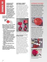
the product ofthe future . This design offers theadvantages of greatly reduced space requirements, lighter weight and ease of installation and maintenance when compared to other electric actuators. When mounted directly to Bray valves, the R > RUGGED ELECTRICACTUATOR FOR ROTARY VALVES300 TO 6,500 LB-INOUTPUT TORQUEBray Controls yearsof proven success in electric actuation, combined with inno- vative engineering, has produced the R The R > 4 is by far the most compact,lowest profile design of any electric actuator delivering comparable torque output. Thorough research and many years of field experience...
Open the catalog to page 2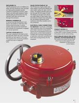
ENCLOSURE ( A ) VALVE STATUS DISPLAY ( D ) > ELECTRICAL CABLE CONNECTIONS ( E ) ( Optional ) > CAPTIVE COVER BOLTS ( C ) > PILOT DRILLED HOLES FOR LOCALCONTROL STATION MOUNTING ( G ) >
Open the catalog to page 3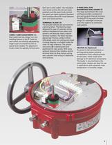
O-RING SEAL FORWATERTIGHT ENCLOSURE ( F ) >
Open the catalog to page 5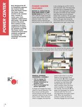
Bray designed the R > 4 to completely separatethe Control Center from the Power Center.The Power Center, located in the actuator base, consists of motor, gear train, capacitor, output drive and heater. This design protects the power drive system as each component has been engineered to require no customer servicing. The Power Centercomponents have been uniquely configured to maintain the extremely low profile of the R > MOTOR ( A ) , CAPACITOR ( B ) ,SPUR GEAR TRAIN ( C ) ANDWORM GEAR ( H ) > MANUAL OVERRIDEHANDWHEEL ASSEMBLY > ٕPull to engage formanual operation.Rotate handwheel toposition valve.ՕPush...
Open the catalog to page 6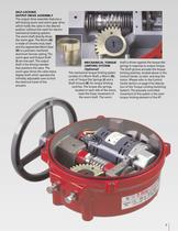
SELF-LOCKINGOUTPUT DRIVE ASSEMBLY The output drive assembly features aself-locking worm and worm gear drive which holds the valve in the desired position without the need for electro- mechanical braking systems. The worm shaft directly drives the worm gear. The Worm ( > G )is made of chrome-moly steel and the segmented Worm Gear ( H ) is a precision machinedaluminum bronze casting. The worm gear and Output Shaft ( > I ) are one part. The outputshaft is the driving member that positions the valve. The worm gear drives the valve status display shaft which operates the infinitely adjustable cams...
Open the catalog to page 7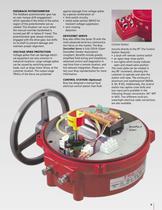
Control Station or below 0 а travel. Thepotentiometer gear always remains engaged with the drive gear, but shifts on its shaft to prevent damage and maintain proper alignment. > FEEDBACK POTENTIOMETER The feedback potentiometer gear hasan overtorque shift engagement which operates if the limits of the active region of the potentiometer are ex- ceeded. This situation can occur when the manual override handwheel is turned past 90 DeviceNet Servo is fully ODVA (OpenDeviceNet Vendor Association) compliant. Benefits include greatly simplified field wiring and installation, advanced control and diagnostics...
Open the catalog to page 9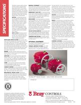
The electric actuator shall be compactand lowprofile to greatly reducespace requirements. The actuatorshall feature ease of access to field wiring and adjustment. The actuatorshall be built to withstand line vibrationand shock without failure and shall bolt directly to Bray valve mountingflanges without using brackets. MANUAL OVERRIDE All units shall be equippedwith an aluminum manual override handwheel torotate the valve without electrical power. The over-ride assembly shall ensure positive and fast manual operation without the use of extra tools or levers. EMERGENCY SHUT-OFF An automatic powercutout...
Open the catalog to page 12All Bray International catalogs and technical brochures
 Series 66 Analog Device Net
3 Pages
 Series 52 Device Net
3 Pages
 Electric Actuators & Accessories
16 Pages
 model FP
8 Pages


Archived catalogs
 Full Product Line Brochure
6 Pages


- Liebherr manual valve
- Liebherr control valve
- Liebherr water valve
- Liebherr ball valve
- Liebherr threaded valve
- Liebherr regulating valve
- Liebherr flange valve
- Liebherr shut-off valve
- Liebherr flap valve
- Liebherr check valve
- Liebherr lever valve
- Liebherr electric valve
- Liebherr valve with handwheel
- Liebherr butterfly valve
- Liebherr valve actuator
- Liebherr chemical product valve
- Liebherr electrically-actuated valve
- Liebherr 3-way valve
- Liebherr rotary valve actuator