


GENERAL CATALOGUE

GENERAL CATALOGUE
Brandoni S.p.A., established in 1961, is a global leader in industrial valve production, with facilities in Italy, China, and Spain. The company is renowned for its innovation, quality certifications, and compliance with European standards.
Brandoni initially produced electromechanical components and diversified in 1985 to become a pioneer in flanged ball valves. By 1995, it adopted a market-oriented strategy, achieving ISO 9002 certification, later updated to UNI EN ISO 9001:2008.
Brandoni invests in R&D and renewable energies. It established ACUAFLOW VALVES S.L. in Spain in 2004 and opened a certified plant in Qian’An, China, in 2006.
The product catalogue includes filtration, shut-off valves, protection check valves, joints, regulation, and solenoid valves, organized by application fields such as water conditioning, gas, heating, drinking water, industry, fire fighting, and marine.
Brandoni products comply with ISO 9001:2008 and various European norms, holding certifications for several countries to ensure high-quality standards and transparency of product origin.
- Shut-off Valves: Conform to EN 1092, ANSI B16.5 #150, and other standards, used in process environments for maintenance ease.
- Ball Valves: Wafer and flanged types, suitable for HVAC, water treatment, and industrial applications, but not for steam or flow regulation.
The catalogue provides technical charts, order sheets, and return forms. Registered users can access detailed technical drawings and pricing information online.
Brandoni S.p.A. leads the industrial valve sector through innovation, quality assurance, and a comprehensive product range tailored to global market needs.
The document outlines specifications for shut-off ball valves, including Series 01-02 inox and Series 03-04 inox, designed for water conditioning, heating, and industrial applications, conforming to directive 97/23/CE PED and various norms.
Valves are made from materials like ASTM A105, AISI 304, AISI 316, and reinforced PTFE, with specific materials for components like the body, ball, stem, and seals.
Valves must be handled with care, installed in the ON or OFF position, and placed between pipe flanges with proper seals. Cross-tightening of bolts is recommended, and welding after installation is discouraged.
Regular maintenance includes replacing O-rings every 24 months and PTFE seats every 48 months, depending on usage. Surfaces should be cleaned periodically to prevent dust accumulation.
Valves should be operated periodically to prevent material build-up. Insulation is recommended for valves exposed to sub-zero temperatures to prevent freezing damage.
The three-way ball valve Series 04 is a TRANS-FLOW valve with a floating ball, requiring pressure to act against the seat of the closed port to prevent leakage and damage.
Options include double and single-acting pneumatic actuators, electric actuators, and gearboxes, with guidance on selecting the right actuator by multiplying the operating torque by a safety coefficient of 1.5.
Includes a pressure/temperature chart indicating maximum pressure and temperature limits for different valve articles, and a Kv-DN chart for flow rates.
Different versions of valves are available, including steel wafer ball valves and flanged ball valves in AISI 316, suitable for various applications such as chemical plants, HVAC, and agricultural uses.
The document outlines various series of shut-off valves, specifically the J9 and L9 series, constructed with materials like EN GJS 400-15, AISI 316, and Aluminium-bronze, with temperature ranges from -10°C to +150°C depending on the liner material.
Installation and maintenance instructions emphasize storing valves in a dry place with the disc partially open, avoiding using the lever or hand wheel for lifting, and not welding flanges to the piping after installation.
Valves conform to standards including EN 558/1-20, EN 1092, ANSI B16.5 #150, EN 593, EN 13445, ISO 5211, EN 12570, and EN 19, with testing conducted in accordance with EN 12266 cat. A (ISO 5208 cat. A).
Before maintenance or dismantling, ensure the system is cooled and depressurized. Avoid using these valves for steam applications and ensure correct installation to prevent damage from water hammers and misalignments.
Includes detailed tables on operating torque, dimensions, and pressure/temperature ratings, with a flow rate/opening position chart and a pressure/temperature chart indicating maximum working pressure decreases with increasing temperature.
Valves are suitable for HVAC, water treatment, industrial uses, and agricultural purposes, designed for both in-line and end-of-line installations, and can be equipped with various actuators and accessories for enhanced functionality.
- Series 20.900 and 21.900 are soft seated gate valves made of ductile iron, conforming to EN ISO 9001 standards, suitable for HVAC, water treatment, and industrial applications.
- Series 18 bidirectional knife gate valves are available in cast iron or stainless steel, suitable for water plants and industries handling viscous liquids.
- Face-to-face dimensions conform to EN558/1.
- Flanges adhere to EN1092 standards.
- Design and testing follow EN1074, EN1171, and EN12266 standards.
- Valves are coated with epoxy, minimum thickness 250 µm, suitable for drinking water.
- Components include materials like EN GJS500-7, AISI 420, and EPDM/NBR for soft seats.
- Valves should be installed in open or closed positions, with careful handling to avoid damage.
- Maintenance allows for O-ring replacement without dismantling the valve body.
- Recommendations include ensuring pipes are clean and using elastic joints to reduce stress.
- Not suitable for steam or flow regulation.
- Maximum pressure for Series 20.900 is 16 bar for DN40-300 and 10 bar for DN350.
- Temperature range for EPDM/NBR seats is -10°C to 70°C.
- Available accessories include ISO 5210 flange kits, electric actuators, and gearboxes.
- Series 18 valves can be equipped with various actuators and accessories for enhanced functionality.
- Series 19: Unidirectional knife gate valves with a compact design, standard rising stem, and easy packing seal replacement, available in cast iron or AISI 316 body with various seal materials suitable for temperatures ranging from -20°C to +300°C.
- Series 23: Bidirectional through blade knife gate valves, designed to prevent material deposit and facilitate maintenance, available with cast iron or stainless steel body, suitable for high-pressure applications up to 100 bar.
- Valves should be installed with care, ensuring proper alignment and avoiding stress on the piping system.
- Regular maintenance includes checking seals and lubricating moving parts, with pneumatic actuators requiring a minimum air supply pressure of 6 bar.
- For electric actuators, weekly checks and lubrication are recommended.
- Series 18.000: Involves dismantling the valve, checking and replacing the 'U' seal and other seals as necessary, and reassembling the valve, with torque specifications for screws provided.
- Series 19.000: Similar to Series 18.000, with additional steps for replacing the packing gland and ensuring proper alignment of packing braids.
- Series 23.000: Follows a similar procedure to Series 19.000, with emphasis on checking seals in both upper and lower parts of the valve.
- Check valves allow liquid flow in one direction, preventing backflow and ensuring circuit integrity when pumps stop.
- Specifications include compliance with EN standards, material details, and application suitability for various industries.
- Valves should be stored in dry conditions and handled with care during installation.
- Recommendations include ensuring proper alignment and avoiding excessive stress on valves to prevent damage.
- Maintenance involves regular checks for leaks and ensuring proper torque on adjustment screws.
The document provides detailed technical specifications and guidelines for various series of check valves manufactured by Brandoni, designed for different industrial applications, including HVAC, water treatment, chemical plants, and food processing.
- Series W6: Disc wafer spring check valves available in two versions: W6.020 with a cast iron body and soft seal, and W6.626 with a stainless steel body and metal/metal seal, suitable for HVAC, water treatment, and industrial applications.
- Series D6: Dual-plate wafer check valves with versions D6.0 (cast iron body) and D6.6 (stainless steel body), suitable for chemical plants and industrial applications.
- Series Y6: Threaded Y check valves with a stainless steel body, suitable for chemical and food processing plants.
- Series 06-M6: Swing wafer check valves with versions 06-M6.4 (carbon steel body) and 06-M6.6 (stainless steel body), suitable for HVAC and industrial applications.
Valves are constructed using materials such as EN GJL 250, ASTM A351 gr. CF8M, AISI 316, and PTFE for various components like the body, disc, spring, and seal, with a detailed breakdown of materials used for each component in different valve series.
Includes pressure/temperature charts for each valve series, indicating maximum working pressure and temperature ranges, highlighting that maximum working pressure decreases as temperature increases.
- Valves can be installed in horizontal or vertical positions, but specific guidelines must be followed to ensure proper operation.
- Maintenance instructions emphasize ensuring pipes and fluids are cooled and depressurized before maintenance.
- Recommendations include avoiding water hammers and ensuring proper alignment to prevent excessive stress on the valves.
Advises on proper storage, handling, and installation practices to ensure the longevity and reliability of the valves, providing safety precautions for handling hazardous fluids and operating at extreme temperatures.
The document serves as a comprehensive guide for selecting, installing, and maintaining Brandoni check valves across various industrial applications, ensuring compliance with international standards and safety regulations.
- Swing Wafer Check Valve: Available in sizes DN 32 to DN 400, with materials including ASTM A351 gr. CF8M and AISI 316, with pressure and temperature ratings varying depending on the material and size, with maximum pressures ranging from 12 to 25 bar.
- Ball Check Valve: Constructed from ductile iron, suitable for non-hazardous liquids, with a temperature range of -10 to 70°C, available in flanged and threaded versions, with sizes from DN 25 to DN 500.
- Flanged Swing Check Valve: Made from cast iron, suitable for HVAC, water treatment, and industrial applications, with a temperature range of -10 to 100°C, and pressure ratings up to 16 bar for smaller sizes.
- Valves should be stored in a dry place and handled with care during installation.
- Ensure correct alignment and flow direction during installation, and do not weld flanges after valve installation.
- For maintenance, ensure the system is depressurized and cooled before disassembly, with some valves featuring removable bonnets for easier maintenance.
- Head loss and flow characteristics are provided for each valve type, with specific Kv values for different sizes.
- Pressure and temperature charts indicate operational limits, emphasizing that maximum working pressure decreases with increasing temperature.
- Use elastic joints to mitigate stresses from water hammers and misalignments.
- Follow specific guidelines for hazardous fluids to ensure safety and compliance with regulations.
The document details the specifications of the "Venturi" check valve, Series M16, and the flanged backflow preventer, Series ECO 3F, designed for water applications, featuring fast closure without water hammers, a hydro-dynamic profile for low head losses, and suitability for various installation positions.
Installation instructions emphasize careful handling, ensuring the valve is installed in the correct flow direction, and avoiding welding flanges post-installation, with minimal maintenance required but precautions advised when dismantling, especially with hazardous fluids.
Valves conform to EN 1092 standards for flanges and are tested according to EN12729 for backflow preventers, with the ECO 3F series homologated in accordance with EN12729 and EN1717 standards.
For the backflow preventer, it is recommended to install a filter upstream to prevent contamination, with installation in accessible, non-flooding areas, and adequate space for maintenance and testing, advising on the use of elastic joints to mitigate stress from water hammers.
Includes detailed dimensions and material specifications for various components of the valves, with head loss data for different flow rates and pressure conditions, emphasizing the importance of correct installation to ensure optimal performance.
Both the check valve and backflow preventer are designed to prevent contamination and ensure safe water distribution, with the backflow preventer particularly crucial in preventing backflow contamination in drinking water systems, with specific installation guidelines to ensure safety and compliance with health regulations.
The document details the specifications for the Series ECO 3F and ECO 3T backflow preventers, designed to prevent contamination of drinking water networks, compliant with EN1717 and EN12729 standards, suitable for use in firefighting and drinking water applications, with the Series ECO 3T available in sizes DN 15 to DN 50, with bodies made of brass or bronze depending on the size.
Maintenance procedures for the relief valve and check valves are outlined, including steps for unscrewing bolts, replacing seals, and reassembling components, with specific spare part codes provided for different models and sizes.
The backflow preventers conform to several standards, including ISO228/1 for threading, EN19 for marking, and EN12729 for testing, manufactured in accordance with EN ISO 9001 quality requirements.
Installation recommendations emphasize the importance of placing the device in accessible, ventilated areas away from potential flooding, advising to install a filter upstream to prevent dirt from affecting the device's operation, with guidance on the correct installation sequence and testing procedures using the ECO3TEST device.
Includes tables listing spare part codes for various components and dimensions for different DN sizes, with a chart providing Kv values and head loss data for different DN sizes, indicating the minimum flow rate required for specific head losses.
Backflow preventers are crucial for preventing contamination in water supply systems, with proper installation and maintenance essential to ensure their effectiveness, highlighting the need for regular checks and the replacement of seals and other components to maintain functionality.
- Material: The valve body is made from EN GJL 250 with an EPDM seal, suitable for temperatures ranging from -10°C to 140°C.
- Coating: Features an internal and external epoxy coating for high temperature resistance.
- Dimensions: Detailed dimensions and weights are provided for DN sizes 65 to 150.
- Continuous pre-regulation for precise control of pressure and flow.
- Self-sealing test points for easy installation of pressure or temperature probes.
- Preset position memory to maintain settings even when the valve is moved.
- Ensure pipes and fluids are cooled and pressure is decreased before maintenance.
- Valves should be installed with the flow direction indicated by the arrow on the body.
- Use suitable gaskets and avoid welding flanges post-installation.
- Regular checks and maintenance should be performed by trained personnel.
- Valves are unidirectional and should be installed respecting the flow direction.
- Pressure tests can exceed the maximum allowed pressure by up to 24 bar at room temperature.
- Flow must be free of cavitation to prevent damage and noise.
- Includes charts for head loss and Kv values for different DN sizes.
- Instructions for setting the hand wheel for easier reading and regulation.
- Guidelines for differential pressure adjustment when using antifreeze mixtures.
- Install thermostats and pressure switches to prevent exceeding temperature and pressure limits.
- Maintain minimum distances between valves and other components to ensure optimal performance.
The document outlines the specifications for the Serie Ekoflux M modulating differential pressure control valve, operating within a temperature range of -10°C to 120°C, suitable for fluids like water and water-glycol mixtures at a maximum pressure of 16 bar, with a pressure/temperature chart indicating that maximum working pressure decreases as temperature increases.
Installation and maintenance procedures emphasize ensuring the cleanliness of piping and valves, proper alignment, and avoiding excessive stress on the valve, with the valve installed on the supply side and connected to the return pipe with a capillary pipe, ensuring that the differential pressure across the user unit is at least twice the value of the differential pressure across the valve to avoid cavitation.
References construction and testing norms such as EN 558-1/1 for face-to-face dimensions, EN1092 for flanges, and EN12266 for testing, with valves suitable for PN 10, PN 16, and PN 25, with specific sizes available in PN 40.
Recommendations include ensuring the system is equipped with thermostats and pressure switches to prevent exceeding temperature and pressure limits, with maintenance performed by trained personnel, and safety precautions observed, especially when dealing with high temperatures or hazardous fluids.
The Kv chart provides flow coefficients for different valve positions and diameters (DN 65, DN 80, DN 100), with the differential pressure chart listing flow rates for various valve models under different pressure conditions, and a detailed table of materials used in the construction of the valves.
Valves should be stored in a dry place, protected from damage, and handled with care, ensuring the valve is clean, undamaged, and correctly oriented according to the flow direction indicated on the body, avoiding welding flanges after installation and using elastic joints to minimize stress.
Instructions for measuring flow rate and regulating differential pressure are provided, including the use of pressure test plugs and the calculation of flow rate using the Kv coefficient, advising on setting the hand wheel for easier reading and adjusting the regulation position using digital setting scales.
Valves are suitable for use in water plants, designed to handle specific pressure and temperature limits, installed horizontally unless specified otherwise, and suitable for drinking or filtered water with a maximum fluid speed of 3.5 m/s for continuous operation.
- The minimal inlet pressure for regulating valves is greater than 0.5 bar (5m H2O).
- A pressure difference exceeding a 3:1 ratio between upstream and downstream can cause cavitation, leading to premature erosion of components, with a cavitation chart for guidance.
- The pilot circuit spring must match operating conditions and respect the allowed regulation range.
- Provides a detailed flow chart for different diameters (DN) indicating low headloss, recommended irrigation/firefighting flow rates, and minimum/maximum allowed flow rates.
- Reduce pressure to a preset value regardless of flow rate and upstream pressure variations, with key ordering information including upstream and downstream pressure values and min/max flow requested.
- Maintain upstream pressure at a preset value and drain excess pressure downstream, with ordering requiring pressure setting values and upstream pressure maintenance details.
- Designed to protect pumping systems from excess pressure due to sudden interruptions, with ordering requiring hydraulic characteristics of the pump and static pressure details.
- Maintain a preset maximum flow rate independently of pressure variations, with the nominal value adjustable by 30% using the pilot setting screw.
- Valves should be stored in a dry, closed place and handled using eye bolts, with regular maintenance including checking and cleaning filters and internal components, and installation requiring careful handling, ensuring no residual parts in piping, and fitting adequate filters and shut-off valves.
- Avoid operating valves under permanent cavitation risk, ensuring proper installation to prevent water hammer damage and maintain unidirectional flow as indicated on the valve body.
- Various series and versions are available, including diaphragm or piston control valves, with specific coatings and pressure ratings, and accessories including pressure gauges, V-ports, and position indicators.
The document details the specifications of needle valves and pressure reducing valves, with the needle valve designed for energy dissipation and cavitation resistance, with materials including EN GJS 400-12, carbon steel, and AISI 304, with dimensions and weight varying by model, and pressure ratings from PN16 to PN64, and pressure reducing valves (Series T15 and F15) made of brass or ductile iron, suitable for water and compressed air, with pressure ratings up to PN25.
Installation and maintenance procedures emphasize careful handling, ensuring cleanliness of piping, and proper alignment, with valves stored in dry conditions and handled using belts or eye bolts, with minimal maintenance due to the design, but removal from piping necessary for interventions.
Valves conform to ISO 228-1 threading and are tested according to EN 1567, with references to D.M. 174 for construction and testing norms.
Recommendations include ensuring pipes and fluids are cooled before maintenance, using filters to protect valves from impurities, and installing manometers to monitor pressure, advising to avoid exceeding a pressure reducing ratio of 5:1 and to use expansion tanks to manage thermal expansion.
Includes charts for head loss coefficients and flow rates, indicating optimal operating conditions, with the cavitation index formula provided to assess cavitation risk, with anti-cavitation devices recommended for high-pressure drops.
Valves are unidirectional, and the flow direction must be respected, highlighting the importance of avoiding water hammer effects and ensuring proper insulation in freezing conditions.
- Purpose: Maintain constant pressure in compressed air circuits and stabilize pressure in distribution networks.
- Versions: Available in PN 10/16, PN 25, and PN 40 with pressure regulation ranges from 1.5 to 12 bar.
- Materials: Body made of EN GJS 400 with epoxy coating, seals made of NBR.
- Construction Norms: Face-to-face dimensions follow EN 558-1/1, flanges conform to EN 1092, and testing is according to EN 1074.
- Installation Recommendations: Install horizontally for optimal performance, ensure piping is clean, and include safety and relief valves as necessary.
- Series 10.000 (Threaded Y Strainer): Made of CF8M stainless steel, suitable for chemical, food, and industrial applications, can be installed horizontally or vertically.
- Series 11.000 (Flanged Y Strainer): Made of CF8M stainless steel, designed for protecting pumps and valves from dirt and solids, not suitable for steam applications.
- Series 50.000 (Strainer Baskets): Prevents aspiration of solids in water inlets and pump suctions, available in galvanized carbon steel or stainless steel.
- General Recommendations: Ensure systems are cooled and depressurized before maintenance, with filters installed to protect against dirt and solids.
- Pressure/Temperature Considerations: Maximum working pressure decreases with increasing temperature, with pressure/temperature charts for guidance.
- Elastic Joints: Protect circuits from movements and absorb vibrations and noise, reducing water hammer effects.
Indirect action solenoid valves operate through a membrane controlled by pressure equilibrium in upstream and downstream branches and a compensation chamber, requiring a minimum input pressure, with mixed action solenoid valves not requiring minimum pressure as the solenoid is directly connected to the membrane.
Store in a closed, dry place.
For inspectionable solenoid valves, internal parts can be disassembled for maintenance, with careful cleaning to avoid damage to components like nuclei, membranes, seals, and seats.
Before maintenance or dismantling, switch off electricity, ensure pipes and fluids are cooled, and pressure is decreased, avoiding temperatures above 50°C and below 0°C.
Handle with care, follow flow direction on the valve body, ensure upstream circuit cleanliness, and match electrical data with supply, installing away from heat in a well-ventilated area, ideally with the coil on top, never supplying electricity to a coil without fitting it to a valve.
Provides dimensions and specifications for various flange types (PN 6, PN 10, PN 16, PN 25, PN 40, ANSI 150) across different DN sizes.
Lists metallic and plastic materials with corresponding standards and designations across different countries.
Details the compatibility of various materials with chemicals, using a legend to indicate suitability (A: Recommended, B: Good, C: Fair, D: Not suitable).
Provides conversion factors for length, area, volume, and weight measurements between different units.
This section provides conversion factors for various units of measurement including torque, energy, power, pressure, and temperature, with key conversions including:
- 1 Newton metre (Nm) is equivalent to 1.355828 pound-foot.
- 1 calorie equals 4.19 Joules.
- 1 horsepower is 745.6999 Watts or 0.7456999 Kilowatts.
- Pressure conversions include 1 Pascal (Pa) to 0.001 kiloPascal (kPa) and 0.000145038 psi.
- Temperature conversions include formulas for converting between Celsius, Fahrenheit, Kelvin, and Reamur.
This section explains the concept of 'total head' or 'piezometric height' in fluid dynamics, based on Bernoulli’s principle, describing how head loss occurs due to friction and turbulence in pipes, quantified using the flowrate coefficient Kv, with higher Kv indicating lower head loss.
This section outlines procedures for placing orders and requesting returns with Brandoni S.p.A., with key points including:
- Orders below €1,000 incur a handling charge of €50, with a minimum order value of €500.
- Packaging costs are 1% of the order volume.
- Declarations of conformity and certificates have specific costs.
- Goods are delivered FCA - Brandoni SpA, with risk transferring to the purchaser upon shipment.
- Returns require prior authorization and are subject to a 10% charge if no manufacturing defect is found.
This section details sales conditions, including:
- Prices are subject to change without notice.
- Warranty for manufacturing defects is two years from shipment, with defects needing to be reported within 8 days.
- Substitution of defective goods is free if a manufacturing defect is confirmed.
Catalog excerpts

VALVOLE INDUSTRIAL!
Open the catalog to page 1
ears r 50 y een in love Fo e b we hav lves a with v Headquarters: via Novara 199 28078 Romagnano Sesia (NO) ITALY Ph. +39 0163 828111 Fax +39 0163 828130 [email protected] www.brandoni.it China: BRANDONI QIAN’AN VALVES CO. LTD. www.brandoni.net.cn Spain: ACUAFLOW VALVES S.L. www.acuaflowvalves.es
Open the catalog to page 2
SOLENOId VALVES Brandoni’s general catalogue is the support that we give to our clientele for clear and easy consultation. It contains all of our history: > 50 years of passion and dedication > 50 years of experience, with some useful advise > 50 years of products, organized by application field
Open the catalog to page 3
Our company keeping up with a changing world Founded in 1961 by Gian Renzo and Pier Francesco Brandoni, the company Fratelli Brandoni produces components for the electromechanical industry supplying companies such as Pirelli, 3 M and CEAT. In 1985, the company diversifies its activities and becomes the first producer of flanged ball valves in cast iron, with extremely innovative characteristics. Until the 90s, the growth of the company was driven mainly by a successful technical approach: • The construction and production of valves according to the strict European standards and norms • Substantial...
Open the catalog to page 4
during 2004, ACUAFLOW VALVES S.L. is founded in Madrid to serve the Spanish market with products related to the water cycle. In 2006, Brandoni opens its plant at Qian’An in China, which has been certified ISO 9001 recently for the production of butterfly valves, ball check valves, soft seated gate valves and filters, products formerly distributed by Brandoni. 2007: In order to enhance service to the fast developing East-European area, Brandoni adheres to the HIdROTECH consortium. TODAY, innovation is the keyword and the driving force that governs Brandoni’s activities, with investments in research...
Open the catalog to page 5
Our production how and where we produce Qian’An represents a starting point for collecting the considerable opportunities offered by the huge Chinese market with its keen interest in quality products.
Open the catalog to page 6
The new production line goes along with the consolidated production of ball valves, backflow preventers, check valves and balancing valves in Romagnano Sesia, where new painting plant and new automatic machinery have been recently installed, as well as equipment for testing of the backflow preventers. Along with production, Brandoni is also engaged in trading (items in in stainless steel, expansion joints, knife gate valves) granting the service of one of the most complete catalogues in the industrial valve sector.
Open the catalog to page 7
To make consultation easier, we have listed some useful information. > Icons that relate to certification, application fields and origin of the products. > Information available on our web-site www.brandoni.it > A technical section containing measurement and conversion charts. > Some indications on how to place the order in response to your frequent requirements. Information you can find on our website On our website www.brandoni.it, you can find information about our range, to help you select the right product. On selecting "HOME", you can download the following: Aecatfi alls Inforniazlonl Catalogs...
Open the catalog to page 8
Certification Brandoni S.p.A. Industrial valves has been one of the first companies in the Valsesia area to obtain the quality certification according to ISO 9002, recently modified into UNI EN ISO 9001 – Version 2008. All kinds of machinery for the production comply with the most severe European norms with certification of the products for approval dIN-dVGW for gas: EN 12729 and WRAS for backflow preventer and guideline 97/23/CE(PEd). ISO 9001-2008 Certification Brandoni S.p.A. - Italy Brandoni also obtained the requested certifications ISO 9001-2008 Certification Brandoni Qian’An Valves Co....
Open the catalog to page 9
Shut-off valves Shut-off valves are largely installed in process environments, and in the sectioning of the plant for easy maintenance. dRINKING WATER FIRE FIGHTING
Open the catalog to page 10
Ball valves Series Bl Series 01-02 stainless steel 42 Series 03-04 stainless steel 50 Butterfly valves Series J9 Soft seated gate valves Series 20.900-21.900 Accessories for butterfly valves Instructions / Recommendations / Accessories for soft seated gate valves Knife gate valves Series 18 86 Accessories for knife gate valves
Open the catalog to page 11
Wafer cast iron ball valve Shut-off valves Application fields dRINKING WATER FIRE FIGHTING
Open the catalog to page 12
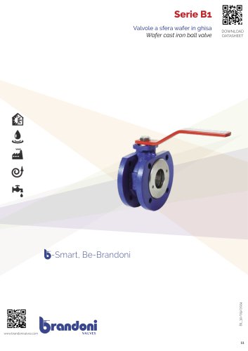
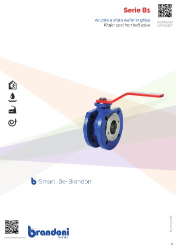
Serie B1 Series B1 consists of wafer-ball-type shut-off valves, with the body in cast iron and a floating ball, manufactured in accordance with the severe product standards and the quality management of ISO 9001. Suitable for heating and conditioning (HVAC), district heating, distribution and water treatment, industrial applications, agricultural applications, for compressed air processing, for oils and hydrocarbons. YES: for installation in-line and end of line, for services with frequent acting, the integrated ISO 5211 support allows the installation of a wide range of actuators . The B1 wafer...
Open the catalog to page 13
Shut-off valves Wafer cast iron ball valve
Open the catalog to page 14
Serie B1 Materials Material Body Flange Ball Ball seat Stem Sliding washer Ring O-ring Lever Stop plate Spring washer Nut EN GJL 250 EN GJL 250 Brass CuZn40Pb2 chrome plated / AISI304 / AISI316 Reinforced PTFE Brass CuZn40Pb2 / AISI304 / AISI316 PTFE Brass CuZn40Pb2 / AISI304 / AISI316 NBR / FKM (Viton®) Epoxy coated carbon steel Galvanized carbon steel Galvanized carbon steel Galvanized carbon steel Shut-off valves N.B.: In order to choose the right actuator, we recommend multiplying the operating torque figure by a safety coefficient, K=1.5
Open the catalog to page 15
Wafer cast iron ball valve Temperature Maximum pressure Fluids * Shut-off valves NB: the maximum working pressure decreases while the temperature increases; please refer to “pressure/temperature” chart G1, L1, G2, L2: see chart to side *: Hazardous gas, liquids (explosive, inflammable, toxic) in accordance with 97/23/CE PED and 67/548/EEC Liquid - steam saturation line (fluid: water) Head loss Fluid: water (1m H2O = 0,098bar) RANGE NOT SUITABLE FOR STEAM. DO NOT use when temperature and pressure are below the liquid-steam saturation line ( hatched area )
Open the catalog to page 16All Brandoni catalogs and technical brochures
 SERIES B1_2024
10 Pages
 B-Smart 2019
40 Pages
 Technical Catalog 2018
468 Pages
 SERIES D6
6 Pages
 SERIES W6
8 Pages
 SERIES 18
8 Pages
 SERIES EKOFLUX.L
6 Pages
 SERIES 20E900
8 Pages
 SERIES 20.900-21.900
10 Pages
 SERIES J9.0
13 Pages
 SERIES L9
14 Pages
 SERIES J9
12 Pages
 SERIES 03-04 INOX
14 Pages
 SERIES 02.622
8 Pages
 SERIES 01.622
6 Pages
 SERIES 01.411
8 Pages
 SERIES 04.1
10 Pages
 SERIES B2.7
14 Pages
 B-Smart
40 Pages
 SERIES B2.3
12 Pages
 SERIES B2.1
12 Pages
 Serie Ekoflux L
6 Pages
 Serie B2.1
12 Pages
 Smart 2017
40 Pages
Archived catalogs
 Series B1_2018
12 Pages