- Catalogs
- BRAND HYDRAULICS
- Series 36
Series 36
1 /10Pages

Series 36
1 /10Pages
Catalog excerpts
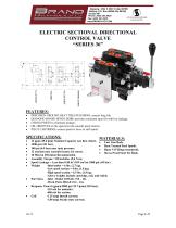
ELECTRIC SECTIONAL DIRECTIONAL CONTROL VALVE • PRECISION GROUND HEAT TREATED SPOOL assures long life. • DIAMOND HONED SPOOL BORE provides consistent spool fit with low leakage. • O'RING PORTS to eliminate leakage. • OIL GROOVES on the spool provide smooth spool motion. • PILOT CARTRIDGE assures positive force to shift spool. SPECIFICATIONS: MATERIALS: 12 gpm (45.4 1pm) Nominal Capacity (see flow chart). # Cajjt Iron Body 3500 psi (241 bar). . Heat Treated Steel Spools. 100 psi (6.9 bar) max tank pressure. . Buna N O'Rings (standard). 12 sections max (consult factory for more). . Stress proof ^ Tie Rods 10 Micron Filtration Recommended. Assembly Torque = 85 inch-lbs. (9.6 N m) Spool Leakage = Less than 0.50 in3 (819 cm3)at 1000 psi. (69 bar) -High spool section = 6.5 lbs. (2.9 kg). -Above weights include cartridge, coil, and reliefs. Port Sizes -Inlet / Outlet #10SAE (7/8 - 14). Coil -1.25 amp Inrush current. -1.00 amp Steady state current.
Open the catalog to page 1
SERIES 36 – GENERAL INFORMATION: The Brand, Series 36 Electric Sectional Directional Control Valves are assembled to meet our customer’s requirements for up to twelve individual applications per assembly. Brand Hydraulics does not charge extra for this assembly process, an assembly is priced solely on the overall sum of the prices of its components. The Series 36 is available with electric unloading in the inlet section. The flow goes directly to tank in the neutral condition. Neutral flow does not pass through the spool sections; therefore, the neutral pressure drop to tank remains low and constant...
Open the catalog to page 2
SERIES 36 – GENERAL INFORMATION CONT… HIGH SPOOL SECTIONS – offer the same options as listed for the low sections with the addition of individual port reliefs. Three types of reliefs are offered for high sections machined with port relief cavities – ball spring (B), area-differential (R), or area-differential with anti-cavitation check (C). The high section can also be made with a pilot-operated double lock (36BL2F). END SPOOL SECTIONS – are the last spool section of an assembly. The end section is not an outlet and it does not have cross-holes drilled all the way through the casting. ELECTRIC/MANUAL...
Open the catalog to page 3
EXAMPLES OF COMMON MODEL CODES CONT… 36BHFXC20P………….. Blocked spool, center section, combo area-differential and anti-cavitation relief set at 2000 psi (138 bar) on port A, port B has a cavity plug (no relief), and spring center. TIE ROD KITS: 36TR1…………………... Tie rod kit for valve stack containing a standard inlet and one spool section. 36TR2……………………Tie rod kit for valve stack containing a standard inlet and two spool sections. 36TR3…………………... Tie rod kit for valve stack containing a standard inlet and three spool sections. STANDARD ASSEMBLY MODEL CODES: 36A1……………………. Single spool assembly, 36BFXB...
Open the catalog to page 4
SERIES 36 – CREATING A MODEL CODE FOR SERIES 36 CONT… HIGH SPOOL SECTION WITH DOUBLE LOCKS: 3 6 B L 2 F __ __ __ __ __ SPOOL: Y – Open X – Blocked END SECTION: Omit – Center section B – End section W – End section, used with auto unloading and power beyond (36TG2WA) OPTIONS: A – Automatic unloading C – Clevis use w/ closed inlet CA – Clevis use w/ automatic unloading H – Manual handle use w/ closed inlet HA – Manual handle use w/ automatic unloading M – Manual override stroke control. Choose (A) or (B) port or both. O – Spring offset NW – No wire through spool D – Spring center (P to A) / detent...
Open the catalog to page 5
SERIES 36 FLOW AND PRESSURE INFO: Pressure vs. Flow for Inlet Relief Pressure Drop vs. Flow for S36 Relief Flow (lpm) Pressures taken from one spool double lock section. The pressure drop is the difference between the inlet pressure and the pressure at port A or B of noted section. 360 Pressure drop is the dif ference between the pressure at the work port and the outlet pressure f or noted spool section. Neutral Flow Pressure Drop Pressure Drop vs. Flow for A or B to T 0.0 Pressure Drop vs. Flow for P to A or B Press. Drop vs. Flow for Double Lock Sect. 3.8
Open the catalog to page 7
DIMENSIONAL DATA: Inches & [millimeters] RELIEF ADJUSTMENT
Open the catalog to page 8
SERIES 36/38 SWITCH WIRING DIAGRAM: THE ABOVE WIRING DIAGRAM IS FOR A THREE SPOOL VALVE. TO WIRE MORE SECTIONS, REPEAT THE WIRING FOR EACH SECTION AS NOTED. (DPDT) DOUBLE-POLE DOUBLE-THROW SWITCH(S)
Open the catalog to page 9
VALVE ASSEMBLY ARRANGEMENT: 36A_______________________________________ PRICE INLET/OUTLET DISTIBUTOR:_________________________________________________________________ ADDRESS:____________________________________________________________________ CITY:___________________STATE:________ZIP:_________DATE:___________________
Open the catalog to page 10All BRAND HYDRAULICS catalogs and technical brochures
 V0200100000
3 Pages
 V0100080000
3 Pages
 V0100060000
3 Pages
 V0100040000
3 Pages
 V0100020000
3 Pages
 BRAND Hydraulics - EC-12-02
4 Pages
 FC 0-30 gpm (0-114 lpm)
4 Pages
 BRAND Hydraulics - SHV
1 Page
 Series 84
1 Page
 BRAND Hydraulics - DS
7 Pages
 RP01000003
5 Pages
 RP01000002
5 Pages
 84 series
1 Page
 LEFC
LEFC4 Pages
 83 series
1 Page
 V100
V1003 Pages
 RP01000001
5 Pages
 POC76
POC761 Page
 SEFC
SEFC2 Pages
 36EFC
36EFC4 Pages
 Series38
10 Pages
 Series 34
10 Pages
 MS6
MS62 Pages
 Series 21
7 Pages
 DS
DS7 Pages
 BRAND Hydraulics - MS
2 Pages
 SDCF
SDCF4 Pages
 45 and 120 gpm (170-454 lpm)
3 Pages
 30-45 gpm (114-170 lpm)
2 Pages
 0-30 gpm
4 Pages
 0-90 gpm (0-341 lpm)
2 Pages
 Custom Electronic Packages
3 Pages
 EC20300
10 Pages
 EC20100
7 Pages
 EC0004A
7 Pages
 EC20400
8 Pages
 EC20200
8 Pages
 EC-12-02
4 Pages
 EC-12-01
4 Pages
 DC
DC4 Pages
 AO
AO4 Pages
 B300
B3001 Page
 B series
2 Pages
 FG
FG2 Pages
 INTERFACE CARD
7 Pages
 "TS" Catalog
5 Pages
 PC - Pilot check valve
2 Pages


- Electrically operated valve
- Flap valve
- Check valve
- Direct-operated solenoid valve
- Hydraulic pump
- Hydraulic directional control valve
- Hydraulic piston pump
- Relief valve
- Spool hydraulic directional control valve
- Electrically-operated hydraulic directional control valve
- Hydraulic check valve
- Manually-controlled hydraulic pump
- Manual hydraulic directional control valve
- Pilot-operated relief valve
- Compact hydraulic directional control valve
- Compact check valve
- Hydraulic solenoid valve
- 4-way hydraulic directional control valve
- Lever-operated hydraulic directional control valve