
- Catalogs
- BRAND HYDRAULICS
- SECTIONAL DIRECTIONAL CONTROL VALVE “SERIES 34”

SECTIONAL DIRECTIONAL CONTROL VALVE “SERIES 34”

SECTIONAL DIRECTIONAL CONTROL VALVE “SERIES 34”
- Includes individual load check to prevent load dropping.
- Durable precision ground chrome plated spool.
- Diamond honed spool bore for consistent fit and low leakage.
- Adjustable handles and O-ring ports to prevent leakage.
- Offers parallel or series flow paths with power beyond capability.
- 100% tested for internal and external leakage and flow.
- Nominal capacity: 12 gpm (45.4 lpm).
- Maximum pressure: 3500 psi (241 bar).
- Maximum tank pressure: 400 psi (27 bar).
- Maximum sections: 12 (consult factory for more).
- Recommended filtration: 10 Micron.
- Assembly torque: 85 inch-lbs. (9.6 N m).
- Material: Cast iron body, hard chrome plated steel spools, Buna N O-rings.
- Low Spool Sections: Available in open center, tandem center, and tandem with metering configurations. Various spool actions and actuator options are available.
- High Spool Sections: Similar to low spool sections but with additional features like individual port reliefs.
- Various seal kits are available for different valve attachments and spool sections.
- Detent kits include three-position and two-position options.
- Multiple styles of handle kits are available, including bent or straight handles.
- Flow control options include pressure compensated and non-pressure compensated types.
- Detailed assembly instructions for valve sections, including tie rod kits and torque specifications.
- Pressure drop analysis with graphs illustrating pressure drop versus flow for various configurations.
- Relief cartridges available with specific pressure settings, adjustable in increments of 100 psi.
- Custom options or accessories can be discussed with the factory.
Catalog excerpts
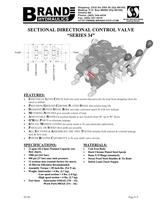
Certificate #02.002.1 ISO 9001:2008 WITH DESIGN 02-08 Page E-9 A B A B A B 34PG1B 34BLFO4SG 34BFT4SB 34BHFT4YR**R** 34TG1 PUMP TANK SECTIONAL DIRECTIONAL CONTROL VALVE “SERIES 34” FEATURES: „h INDIVIDUAL LOAD CHECK built into each section that prevents the load from dropping when the spool is shifted. „h PRECISION GROUND CHROME PLATED SPOOL that assures long life. „h DIAMOND HONED SPOOL BORE provides consistent spool fit with low leakage. „h METERING NOTCHES give smooth control of load. „h ADJUSTABLE HANDLES position handle in any location from 90„a up to 90„a down. „h O’RING PORTS to eliminate leakage. „h SPECIAL MODIFICATIONS are easily made to fit your particular application. „h PARALLEL OR SERIES flow paths are possible. „h ALL SECTIONS & ASSEMBLIES ARE 100% TESTED includes both internal & external leakage tests & flow tests. „h POWER BEYOND CAPABILITY to fit your multi-valve circuits. SPECIFICATIONS: „h 12 gpm (45.4 lpm) Nominal Capacity (see flow chart). „h 3500 psi (241 bar). „h 400 psi (27 bar) max tank pressure. „h 12 sections max (consult factory for more). „h 10 Micron Filtration Recommended. „h Assembly Torque = 85 inch-lbs. (9.6 N m). „h Weight -Inlet/outlet = 6 lbs. (2.7 kg). -Low spool section = 4 lbs. (1.8 kg). -High spool section = 6 lbs. (2.7 kg). „h Port Sizes -Inlet/outlet #10SAE (7/8 – 14). -Work Ports #8SAE (3/4 – 16). MATERIALS: „h Cast Iron Body. „h Hard Chrome Plated Steel Spools „h Buna N O’Rings (standard). „h Stress Proof Steel Handles & Tie Rods „h Delrin Load Check Poppet
Open the catalog to page 1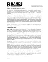
Directional Control Valves Page E-10 SERIES 34 – GENERAL INFORMATION: The Brand, Series 34 Sectional Directional Control Valves are assembled to meet our customer’s requirements for up to twelve individual applications per assembly. Brand Hydraulics does not charge anything extra for this process and assembly is priced solely on the overall sum of the prices of its components. When assembled in their normal manner the series 34 spool sections are in parallel. When the spools are in neutral position the flow passes by each spool and then onto the tank (outlet) port. If two or more spools are shifted...
Open the catalog to page 2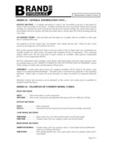
Directional Control Valves Page E-11 SERIES 34 – GENERAL INFORMATION CONT… OUTLET SECTION – is available end ported (1) which is not convertible to top port, or top ported (2) which is field convertible to end ported. Available machined for power beyond but without power beyond cartridge (A), machined for power beyond and with the power beyond cartridge (B), closed center plug (C) not available with power beyond, and field convertible open to closed center (D) without breaking open the valve stack. ACCESSORY ITEMS – both mid-inlets and mid-outlets are available, both are available as either split...
Open the catalog to page 3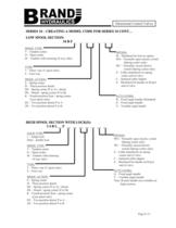
Directional Control Valves Page E-13 SPOOL TYPE: T – Tandem center O – Open center M – Tandem with metering (4-way only) SERIES 34 – CREATING A MODEL CODE FOR SERIES 34 CONT… LOW SPOOL SECTION: 34 B F __ __ __ __ __ __ __ HIGH SPOOL SECTION WITH LOCK(S): 3 4 B L __ F __ __ __ __ __ __ __ SPOOL TYPE: T – Tandem center O – Open center M – Tandem with metering (4-way only) TYPE: 3 – Three–way (T spool only) 4 – Four-way OPTION: M – Machined for bolt on option WO – Normally open electric switch (Spring center only) WC – Normally closed electric switch (Spring center only) Z – Cable attachment on...
Open the catalog to page 5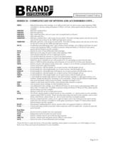
Directional Control Valves Page E-15 SERIES 34 – COMPLETE LIST OF OPTIONS AND ACCESSORIES CONT… 34B10…………….. High lift ball spring relief cartridge, set at 1000 psi (69.0 bar), for spool section codes beginning 34BH. (Available in pressure setting increments of 100 psi (6.9 bar), please specify desired setting as per this example). 34BFMIC…………Mid-inlet combined flow. 34BFMIS…….……Mid-inlet split flow. 34BFMOI…….…...Mid- outlet/inlet (flow exits out A port, and is accepted back in at B port). 34BFMOS……….. Mid-outlet split flow. 34BHFMIC……….Mid-inlet, combined flow, with cavities for port reliefs....
Open the catalog to page 7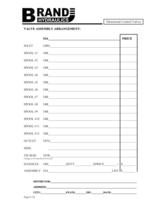
Directional Control Valves Page E-18 VALVE ASSEMBLY ARRANGEMENT: 34A_____________________________________________ PRICE INLET 34PG_______________________________________________________ SPOOL #1 34B________________________________________________________ SPOOL #2 34B________________________________________________________ SPOOL #3 34B________________________________________________________ SPOOL #4 34B________________________________________________________ SPOOL #5 34B________________________________________________________ SPOOL #6 34B________________________________________________________...
Open the catalog to page 10All BRAND HYDRAULICS catalogs and technical brochures
 V0200100000
3 Pages
 V0100080000
3 Pages
 V0100060000
3 Pages
 V0100040000
3 Pages
 V0100020000
3 Pages
 BRAND Hydraulics - EC-12-02
4 Pages
 FC 0-30 gpm (0-114 lpm)
4 Pages
 BRAND Hydraulics - SHV
1 Page
 Series 84
1 Page
 BRAND Hydraulics - DS
7 Pages
 RP01000003
5 Pages
 RP01000002
5 Pages
 84 series
1 Page
 LEFC
LEFC4 Pages
 83 series
1 Page
 V100
V1003 Pages
 RP01000001
5 Pages
 POC76
POC761 Page
 SEFC
SEFC2 Pages
 36EFC
36EFC4 Pages
 Series38
10 Pages
 Series 36
10 Pages
 Series 34
10 Pages
 MS6
MS62 Pages
 Series 21
7 Pages
 DS
DS7 Pages
 BRAND Hydraulics - MS
2 Pages
 SDCF
SDCF4 Pages
 45 and 120 gpm (170-454 lpm)
3 Pages
 30-45 gpm (114-170 lpm)
2 Pages
 0-30 gpm
4 Pages
 0-90 gpm (0-341 lpm)
2 Pages
 Custom Electronic Packages
3 Pages
 EC20300
10 Pages
 EC20100
7 Pages
 EC0004A
7 Pages
 EC20400
8 Pages
 EC20200
8 Pages
 EC-12-02
4 Pages
 EC-12-01
4 Pages
 DC
DC4 Pages
 AO
AO4 Pages
 B300
B3001 Page
 B series
2 Pages
 FG
FG2 Pages
 INTERFACE CARD
7 Pages
 "TS" Catalog
5 Pages
 PC - Pilot check valve
2 Pages


- Electrically operated valve
- Flap valve
- Check valve
- Hydraulic pump
- Direct-operated solenoid valve
- Hydraulic directional control valve
- Hydraulic piston pump
- Spool hydraulic directional control valve
- Electrically-operated hydraulic directional control valve
- Manual hydraulic directional control valve
- Hydraulic check valve
- Manually-controlled hydraulic pump
- Compact hydraulic directional control valve
- Pilot-operated relief valve
- Compact check valve
- Hydraulic solenoid valve
- 4-way hydraulic directional control valve
- 3-way hydraulic directional control valve