
Catalog excerpts

ISO 9001:2000 WITH DESIGN Certificate #02.002.1 EC0004A: INTERFACE CARD FEATURES: Din rail mount, Din35 and Din 32. Reverse polarity protection Short circuit protection Pulse Width Modulated Output. Current controlled output, maintains output current regardless of supply voltage and coil resistance variations. Capable of accepting four industry standard signal types: Potentiometer, 0-10V, 0-5V, or 4-20mA. Reference voltage provided for control via an external potentiometer. Proportional Indicators for Input signal and Output signal, plus an on/off power and potentiometer status indicator. Two Enable lines are provided, one with adjustable soft stop, both with adjustable soft start. (See details on page 3 and 4) Independent ramp adjustments up and down, 0.1 -12 seconds. Maximum current adjustment does not affect the Minimum current adjustment. Wide voltage supply range 12-30 VDC APPLICATION: The EC0004A conveniently interfaces a PLC or transducer with a proportional solenoid. DESCRIPTION: The EC0004A has been designed to meet the various requirements of mobile and industrial hydraulic control applications. EC0004A cards are versatile, cost effective and easily integrated into new or pre-existing designs. Much of this is a result of the unique ability each card has to accept 4 different signals. The EC0004A can accept any of the following input types: Potentiometer, 0-10V, 0-5V, or 4-20mA. The card takes these signals and converts them into a PWM output suitable for a Brand EFC-Series valve or other proportional valves that meet the proper specifications. GENERAL SPECIFICATIONS: Voltage Supply Operating Temperature Storage Temperature Max Continuous Output Current Output Type Frequency Weight, fully assembled Page A-34 12-30 VDC -40C - 70C (-40F - 158F) -40C - 70C (-40F - 158F) 2.5 Amps PWM , Pulse Width Modulation, 0-100% Duty cycle 107Hz +/- 5 Hertz 0.151kg (0.332lb.) 02-08
Open the catalog to page 1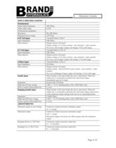
Electronic Controls INPUT SPECIFICATIONS: Potentiometer Wiper Input Impedance Wiper Input range Potentiometer guidelines Resistance Minimum Power rating 0-10 Volt Input Input Impedance Step response 0-5 Volt Input Input Impedance Step response 4-20mA Input Input Impedance Step response Enable Input Impedance High state EN pin voltage Source current while pulled low Ramping Enable Input Impedance High state REN pin voltage Source current while pulled low 10K Ohms 0-10V 2K-10K Ohms 1/8th Watt Terminal block 2, Pin 9 10K Ohms Output current will equal: ((Input voltage x 0.1) (max current - min...
Open the catalog to page 2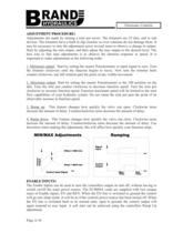
Electronic Controls ADJUSTMENT PROCEDURE: Adjustments are made by turning a trim pot screw. The trimmers are 25 turn, end to end devices. The trimmers have a built in slip clutches so over rotations do not damage them. It may be necessary to turn the adjustment screw several turns to observe a change in output. Start by adjusting the min output, and then adjust the max output to the desired level. The best way to fine tune adjustments is to observe the function response or speed. It is important to make adjustments in the following order. 1. Minimum output: Start by setting the master...
Open the catalog to page 3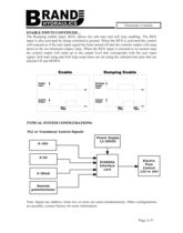
Electronic Controls ENABLE INPUTS CONTINUED... The Ramping enable input, REN, allows for soft start and soft stop enabling. The REN input is also activated by being switched to ground. When the REN is activated the control will respond as if the user input signal has been turned off and the controls output will ramp down to the set minimum output value. When the REN input is returned to its normal state the control output will ramp up to the output level that corresponds with the user input signal. Soft start ramp and Soft stop ramp times are set using the onboard trim pots that are Ramping...
Open the catalog to page 4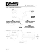
Electronic Controls EC/EFC – SERIES SCHEMATIC DRAWING: EC-Series Electronic Controller Analog Signal Voltage Source EFC Valve EX 3-Port=Excess flow is usable and pressure compensated. The flow can also be ran to tank. CF Controlled flow priority port, Pressure compensated 2-Port=This port is plugged. PUMP TANK 3-Port=Fixed displacement 2-Port=Pressure compensated DIMENSIONAL DATA: inches & [millimeters] 3.53" [89.60] 5.20" [132.08] 2.00" [50.76] 2.03" [51.44] 0.60" [15.33] Mounts 0nto Din 35 or Din 32. Din rail not included, see accessories listing. Page A-38
Open the catalog to page 5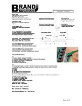
Electronic Controls Power LED LED indicates when board has DC voltage connected. LED turns off when the enable input becomes active (switched low). Input Signal LED Proportional to the level of input signal. Output Signal LED Proportional to the level of output current. P.F.P. Potentiometer Fault Protection A saftey feature: P.F.P will shutdown the boards wiper input if the potentiometer ground becomes open or disconnected. Ramping Down Clockwise: Increases the Outputs Ramp off time. Maximum Output Adjustment Clockwise: Increases Output Ramping Up Clockwise: Increases the Outputs Ramp on...
Open the catalog to page 6All BRAND HYDRAULICS catalogs and technical brochures
-
V0200100000
3 Pages
-
V0100080000
3 Pages
-
V0100060000
3 Pages
-
V0100040000
3 Pages
-
V0100020000
3 Pages
-
BRAND Hydraulics - EC-12-02
4 Pages
-
FC 0-30 gpm (0-114 lpm)
4 Pages
-
BRAND Hydraulics - SHV
1 Pages
-
Series 84
1 Pages
-
BRAND Hydraulics - DS
7 Pages
-
RP01000003
5 Pages
-
RP01000002
5 Pages
-
84 series
1 Pages
-
LEFC
4 Pages
-
83 series
1 Pages
-
V100
3 Pages
-
RP01000001
5 Pages
-
POC76
1 Pages
-
SEFC
2 Pages
-
36EFC
4 Pages
-
Series38
10 Pages
-
Series 36
10 Pages
-
Series 34
10 Pages
-
MS6
2 Pages
-
Series 21
7 Pages
-
DS
7 Pages
-
BRAND Hydraulics - MS
2 Pages
-
SDCF
4 Pages
-
45 and 120 gpm (170-454 lpm)
3 Pages
-
30-45 gpm (114-170 lpm)
2 Pages
-
0-30 gpm
4 Pages
-
0-90 gpm (0-341 lpm)
2 Pages
-
Custom Electronic Packages
3 Pages
-
EC20300
10 Pages
-
EC20100
7 Pages
-
EC0004A
7 Pages
-
EC20400
8 Pages
-
EC20200
8 Pages
-
EC-12-02
4 Pages
-
EC-12-01
4 Pages
-
DC
4 Pages
-
AO
4 Pages
-
B300
1 Pages
-
B series
2 Pages
-
FG
2 Pages
-
"TS" Catalog
5 Pages
-
PC - Pilot check valve
2 Pages


