Catalog excerpts

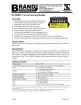
ECM0001: Current Steering Module • Eliminates the need for double pole double throw switches (Bussed Cathode Design) to control a Brand Series 36 or Series 38 stack valve. • Compatible with 12 or 24 VDC systems. • Easy installation with 0.250"quick tab terminals. • Potted enclosure helps protects the internal circuitry from mechanical and environmental stress. • Uses 10% less wire than equivalent DPDT systems.* • Simplifies the replacement of stack valves that do not use an unloaded inlet. • Extends switch contact life; each output terminal has inductive kickback suppression Interface joysticks, switch boxes, and pendant controls with Brand Series 36 or Series 38 stack valves. The ECM0001 was designed to simplify the wiring of Brand Series 36 and Series 38 stack valves. When a switch input is activated a corresponding work section coil terminal and the inlet coil output terminals become energized. The module is set up to run up to a 6-spool stack valve. Two ECM0001 modules can be daisy chained for control of up to 12 *10% savings based on wiring for a 6-section stack valve. Switches are less then 3 inches apart, and located 10 feet from the power source and stack valve. "Inlet coil output terminals must be limited to a combined 2.5A load. The inlet coil output buss current must not exceed 2.5A. *** 5A fuse based on controlling a 1-12 spool Brand Series 36 or Brand Series 38 stack valve.
Open the catalog to page 1
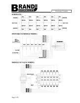
Electronic Controls SCHEMATIC: COIL INLET COIL INLET COIL SWITCH SWITCHES TO MODULE WIRING: SEC. SEC. SEC. SEC. SEC. SEC. (SPDT) SINGLE-POLE DOUBLE-THROW SWITCH(S) (ONE SWITCH PER SECTION) MODULE TO VALVE WIRING: SEC. SEC. SEC. SEC. SEC. SEC.
Open the catalog to page 2
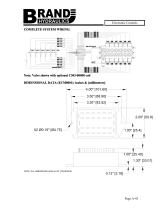
Electronic Controls COMPLETE SYSTEM WIRING: SEC. SEC. SEC. SEC. SEC. SEC. SW 6 Note: Valve shown with optional C503-00000 coil DIMENSIONAL DATA (ECM0001): inches & [millimeters] 1.00" [25.40] 1.30" [33.01] NOTE: ALL DIMENSIONS HAVE ±0.03 TOLERANCE
Open the catalog to page 3
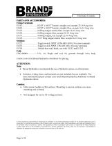
Switches, wiring, fuses, and terminals are not included, but are available. For more information please contact your local Brand Hydraulics distributor or Brand Hydraulics direct. Caution: Only mount module on flat surfaces. Mounting to uneven surfaces can cause mounting ears to break. Not designed for use in AC voltage systems. It is the purchaser's responsibility to determine the suitability of any Brand Hydraulics product for an intended application, and to insure that it is installed in accordance with all federal, state, local, private safety, health regulations, and codes and...
Open the catalog to page 4All BRAND HYDRAULICS catalogs and technical brochures
-
V0200100000
3 Pages
-
V0100080000
3 Pages
-
V0100060000
3 Pages
-
V0100040000
3 Pages
-
V0100020000
3 Pages
-
BRAND Hydraulics - EC-12-02
4 Pages
-
FC 0-30 gpm (0-114 lpm)
4 Pages
-
BRAND Hydraulics - SHV
1 Pages
-
Series 84
1 Pages
-
BRAND Hydraulics - DS
7 Pages
-
RP01000003
5 Pages
-
RP01000002
5 Pages
-
84 series
1 Pages
-
LEFC
4 Pages
-
83 series
1 Pages
-
V100
3 Pages
-
RP01000001
5 Pages
-
POC76
1 Pages
-
SEFC
2 Pages
-
36EFC
4 Pages
-
Series38
10 Pages
-
Series 36
10 Pages
-
Series 34
10 Pages
-
MS6
2 Pages
-
Series 21
7 Pages
-
DS
7 Pages
-
BRAND Hydraulics - MS
2 Pages
-
SDCF
4 Pages
-
45 and 120 gpm (170-454 lpm)
3 Pages
-
30-45 gpm (114-170 lpm)
2 Pages
-
0-30 gpm
4 Pages
-
0-90 gpm (0-341 lpm)
2 Pages
-
Custom Electronic Packages
3 Pages
-
EC20300
10 Pages
-
EC20100
7 Pages
-
EC0004A
7 Pages
-
EC20400
8 Pages
-
EC20200
8 Pages
-
EC-12-02
4 Pages
-
EC-12-01
4 Pages
-
DC
4 Pages
-
AO
4 Pages
-
B300
1 Pages
-
B series
2 Pages
-
FG
2 Pages
-
INTERFACE CARD
7 Pages
-
"TS" Catalog
5 Pages
-
PC - Pilot check valve
2 Pages


