
- Catalogs
- BRAND HYDRAULICS
- EC20400

EC20400

EC20400
- PWM output proportional to joystick deflection.
- Plug and Play stack valve control with switched output for each side of the lever's center position.
- Ergonomic design with weather-tight control package.
- Protection against reverse polarity, short circuit, and over voltage.
- Current controlled output, maintaining output current regardless of supply voltage and coil resistance variations.
- Onboard indicators for input and output signals, power, and joystick status.
- Two enable lines with adjustable soft start and one with adjustable soft stop.
- Independent ramp adjustments (0.1 - 12 seconds).
- Minimum and maximum current adjustment for output span fine-tuning.
- Wide voltage supply range (12-30 VDC).
The EC20400 is designed to proportionally control the speed and direction of hydraulic motors and cylinders, primarily paired with a single section Brand Series 36 EFC.
Description:The EC20400 is a compact, weatherproof joystick control built for harsh environments, offering user-friendly features for versatility and ease of use.
General Specifications:- Voltage Supply: 12-30 VDC
- PWM Output Current: 2.0 Amps Max Continuous
- PWM Output Frequency: 107Hz +/- 5 Hertz
- Switched DC Output Current: 2.5 Amps Max Continuous Each Output
- Environmental Ratings: IP66 / NEMA 4
- Operating Temperature: -40°C to 85°C
Details the pin configuration for E1948 and E1915 output cables, including power supply, ground, enable inputs, and coil outputs.
Internal Layout:Includes terminal block wiring and fuse specifications, with factory settings for ramping and output adjustments.
Adjustment Procedure:- Minimum output: Adjust until function begins to move, then back off slightly.
- Maximum output: Adjust for desired function speed, limited by hydraulic system capabilities.
- Ramp up/down: Adjust for desired delay in valve opening/closing.
Recommends a 10 amp fuse within 18 inches of the power source, with instructions for unused wire management.
Parts and Accessories:- Includes waterproof vent, toggle switch, switch boot seal, and mounting feet kit.
- Ensure all wires are secured and isolated to prevent injury or damage.
- Mount only on flat surfaces and avoid AC voltage systems.
- Adhere to specified voltage and resistance limits to avoid warranty voidance.
Catalog excerpts

• Pulse Width Modulated output proportional to • Plug and Play stack valve control, includes a switched output for each side of the levers center • Precise control in a low profile ergonomic design. • Weather tight control package • Protected against reverse polarity, short circuit, and over voltage conditions. • Current controlled output, maintains output current regardless of supply voltage and coil resistance variations. • On board proportional indicators for input signal and output signal. Also includes an on/off power and joystick status indicator. • Two Enable lines are provided, one with adjustable soft stop, both with adjustable soft • Independent ramp adjustments up and down, 0.1 -12 seconds. • Minimum and Maximum current adjustment for fine tuning the outputs span. • Wide voltage supply range 12-30 VDC, one control for 12 or 24VDC systems. Proportionally control the speed and direction of hydraulic motors and cylinders. The EC20400 was designed primarily to be paired with a single section Brand Series 36 EFC, but other flow controls meeting the appropriate specifications may be used as well The EC20400 is a compact weatherproof joystick control built with high quality long life components that are designed for use in harsh environments. The control comes loaded with user friendly features that provide versatility without sacrificing ease of use.
Open the catalog to page 1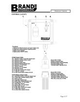
Electronic Controls CONTROL LAYOUT: B Functions 1. Waterproof altitude pressure and vapor realese vent. 2. Single-axis, spring centered, fingertip joystick 3. Master power indicator. 4. Master power ON/OFF switch. E1948 Output Cable Pin 1, Wire #1, Positive 12-30 VDC Supply Input Pin 2, Wire #2, Auxiliary battery output Pin 3, Wire #3, Ground Pin 4, Wire #4, Enable Input Pin 5, Wire #5, Ramping Enable Input Pin 6, Wire #6, "A" Coil Output Pin 7, Wire #7, Ground Pin 8, Wire #8, "B" Coil Output Pin 9, Wire #9, Ground Pin 10, Wire #10, Positive EFC Output Pin 11, Wire #11, Ground Pin 12, Wire Green/Yellow,...
Open the catalog to page 2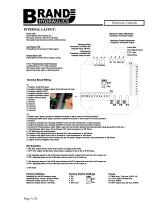
Electronic Controls INTERNAL LAYOUT: Power LED LED indicates when board has DC power present. LED turns off when the enable input becomes active (switched low). Input Signal LED Proportional to the level of input signal. Output Signal LED Proportional to the level of output current. Minimum Output Adjustment Clockwise: Increases Output Maximum Output Adjustment Clockwise: Increases Output Ramping Down Clockwise: Increases the Outputs Ramp off time. Ramping Up Clockwise: Increases the Outputs Ramp on time. Power Red Input Signal Green P.F.P. Red Output Blue P.F.P. Potentiometer Fault Protection...
Open the catalog to page 3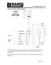
Electronic Controls TYPICAL SYSTEM CONFIGURATION: Orange Black Ramp Enable Brown System Ground Black Blue Black NOTE: Brand Hydraulics recommends a 10 amp fuse be placed within 18 inches of this controls power source. The fuse and power source are customer supplied parts. Valve is sold separately. NOTE: Ensure that all unused wires are capped, and electrically isolated from each other and ground.
Open the catalog to page 4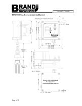
Electronic Controls DIMENSIONAL DATA: inches & [millimeters] Mounting Feet Can Be Rotated Bottom View of Enclosure Mounting Holes (Optional Mounting Method)
Open the catalog to page 5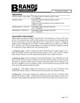
Electronic Controls Adjustments: Minimum output or zero setting Maximum output Clockwise rotation increases minimum output 0 - 1.5 Amps Clockwise rotation increases maximum output 0.05 - 2 Amps Maximum output will always be 50 mA greater then the minimum output Ramping Down, or Fall Time Clockwise rotation increases ramp time 0.1 - 12 Seconds Ramping Up, or Rise Time Clockwise rotation increases ramp time 0.1 - 12 Seconds ADJUSTMENT PROCEDURE: Adjustments are made by turning a trim pot screw. The trimmers are 25 turn, end to end devices. The trimmers have a built in slip clutches so over rotations...
Open the catalog to page 6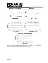
Electronic Controls MIN/MAX Adjustments Ramping Signal Input Control Output Control Output Slope = MAX trim Control Input Signal Output Current vs. Voltage Supply Fluctuation Fall Time Output Regulation vs. Load Resistance (Set point 1 Amp, 26VDC Supply) Rise Time Load Resistance in Ohms Output Current vs. Potentiometer Wiper Input NOTE: Unless stated otherwise the above readings were taken at 25C, with control connected to a 14.6V supply, and the output was set for 1 amp.
Open the catalog to page 7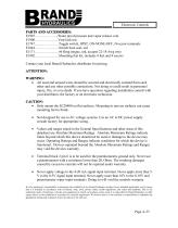
Electronic Controls PARTS AND ACCESSORIES: E1907.………………..Water proof pressure and vapor release vent E1908………………...Vent lock nut E1747…………………Toggle switch, SPST, ON-NONE-OFF, #6 screw terminals E1844…………………Switch boot seal, red E1171…………………#6 Ring tongue, red, accepts 22-18 Awg wire E1902…………………Mounting feet kit, includes 4 feet and 4 screws Contact your local Brand Hydraulics distributor for pricing. ATTENTION: WARNING: All used and unused wires should be secured and electrically isolated from each other and any other possible connections. Not doing so could result in personnel injury, fire,...
Open the catalog to page 8All BRAND HYDRAULICS catalogs and technical brochures
 V0200100000
3 Pages
 V0100080000
3 Pages
 V0100060000
3 Pages
 V0100040000
3 Pages
 V0100020000
3 Pages
 BRAND Hydraulics - EC-12-02
4 Pages
 FC 0-30 gpm (0-114 lpm)
4 Pages
 BRAND Hydraulics - SHV
1 Page
 Series 84
1 Page
 BRAND Hydraulics - DS
7 Pages
 RP01000003
5 Pages
 RP01000002
5 Pages
 84 series
1 Page
 LEFC
LEFC4 Pages
 83 series
1 Page
 V100
V1003 Pages
 RP01000001
5 Pages
 POC76
POC761 Page
 SEFC
SEFC2 Pages
 36EFC
36EFC4 Pages
 Series38
10 Pages
 Series 36
10 Pages
 Series 34
10 Pages
 MS6
MS62 Pages
 Series 21
7 Pages
 DS
DS7 Pages
 BRAND Hydraulics - MS
2 Pages
 SDCF
SDCF4 Pages
 45 and 120 gpm (170-454 lpm)
3 Pages
 30-45 gpm (114-170 lpm)
2 Pages
 0-30 gpm
4 Pages
 0-90 gpm (0-341 lpm)
2 Pages
 Custom Electronic Packages
3 Pages
 EC20300
10 Pages
 EC20100
7 Pages
 EC0004A
7 Pages
 EC20200
8 Pages
 EC-12-02
4 Pages
 EC-12-01
4 Pages
 DC
DC4 Pages
 AO
AO4 Pages
 B300
B3001 Page
 B series
2 Pages
 FG
FG2 Pages
 INTERFACE CARD
7 Pages
 "TS" Catalog
5 Pages
 PC - Pilot check valve
2 Pages


- Electrically operated valve
- Flap valve
- Check valve
- Directional control valve
- Hydraulic pump
- Direct-operated solenoid valve
- Hydraulic directional control valve
- Hydraulic piston pump
- Spool hydraulic directional control valve
- Relief valve
- Electrically-operated hydraulic directional control valve
- Manual hydraulic directional control valve
- Manually-controlled hydraulic pump
- Hydraulic check valve
- Compact hydraulic directional control valve
- Pilot-operated relief valve
- Compact check valve
- Hydraulic solenoid valve
- 4-way hydraulic directional control valve
- 3-way hydraulic directional control valve