Catalog excerpts

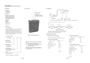
DL200 User's Manual CONTENTS 1. Overview 1.1 Introduction DL200 is a data logger which can connect up to 247 Network Temperature Controllers Model NC200. This unit can write all commands and read all data to and from each Network Temperature Controllers Model NC200 after equipping the unit with a HMI or PC via RS-232 port. The unit provides a dry contact which will be closed when one or more of the Network Temperature Controllers Model NC200 are outside of high and low limits or hardware failure occurs. Power Input 4: 90 ~ 250 VAC, ~ 63 HZ 47 1. RS-232, Modbus protocol 9: Special order Communication 1: Form A Relay, 2A/250VAC Alarm Output DL200- 0: No special option Options Standard ordering code = DL200-4110 1.2 Ordering Code 1.3 Front Panel Figure 1 Front Panel Description The dual-color LED on the front panel provides following status: Green: All the controllers in the network are within their temperature limits and no failure exist. Red: One or more of the controllers are outside of high and low limits, or hardware failure exist. Off: Power is not supplied. Two green LEDs on the front panel will be flashing when data are being received from HMI or transmitted to HMI or PC via RS-232 port. 2. Installation T PWR(G) CAT. II 90-264VAC 47-63HZ 10VA RS- L N HMI or PC 90 ~ 250 VAC FUSE NC200 #1 NC200 #2 9-pin RS-232 port Female 9-pin D-SUB AL(R) COMM IN COMM OUT COMM IN COMM OUT Figure 2 System Wiring In addition to two screw holder located at two corners of the for wall mount installation, a DIN rail clamper provided on the side of the housing for DIN rail mount installation. 3. Modbus Communication 3.1Modbus Functions Supported Only function 03, 06 and 16 are available for this unit. The message formats for each function are described as follows: Query ( from master ) Response ( from slave ) Slave address (20) Function code (3) Starting address of register Hi Starting address of register Lo No. of words Hi (0) No. of words Lo (1-127) CRC16 Hi CRC16 Lo Byte count Data 1 Hi Data 1 Lo Data 2 Hi Data 2 Lo CRC16 Hi CRC16 Lo Function 03: Read Holding Registers 5. Specification UMDL200B 1 1.1 Introduction 1.2 Ordering Code 1.3 Front Panel 1. Overview 3. Modbus Communication 2. Installation 3.1 Modbus Functions Supported 3.2 Modbus Exception Responses 3.3 Modbus Parameter Table 3.4 RTU Communication Examples 4. Operation 4.1 ONLINE 4.2 CODE 4.3 Alarm Output Dual-color LED Green LEDs R: Receive from master T: Transmit to master
Open the catalog to page 1
3.2 Modbus Exception Responses 3.3 Modbus Parameter Table Exception Code Name Cause 1 Bad function code Function code is not supported by the controller Illegal data address Illegal data value Register address out of range Data value out of range or attempt to write a read-only or protected data 2 3 If the unit receives a message which contains a corrupted character (parity check error, framing error etc.), or if the CRC16 check fails, the unit ignores the message. However, if the unit receives a syntactically correct message which contains an illegal value, it will send an exception...
Open the catalog to page 2All BRAINCHILD ELECTRONIC CO. catalogs and technical brochures
-
Open_Panels
3 Pages
-
USB - RS422/485 Converter
1 Pages
-
PID Controller BTC-9090
2 Pages
Archived catalogs
-
CR06 Hybrid Recorder
2 Pages


