

- Products
- Catalogs
- News & Trends
- Exhibitions
Introduction to Bourns® TISP® Telecom Overvoltage Protectors

Introduction to Bourns® TISP® Telecom Overvoltage Protectors
This document provides an in-depth analysis of Bourns TISP® thyristor Surge Protective Devices (SPDs), focusing on their evolution, functionality, silicon structure, electrical characteristics, ratings, and variants.
SPDs are designed to limit overvoltages by diverting excess current. They exhibit either clamping or switching characteristics, with TISP® devices featuring a discontinuous switching action between high and low voltage regions.
The TISP® was developed to meet British Telecom's requirements for integrated overvoltage protection in telephone exchanges, achieved through a planar structure with a buried ion-implanted layer.
The document details the unidirectional thyristor protector's structure, manufacturing process, and the significance of junction termination technologies like planar and glass mesa.
Ensuring precise voltage control is crucial, with ion-implantation used to maintain accuracy within specified voltage windows.
The voltage-current characteristic is explained using a lumped equivalent circuit, detailing the protector's operating modes and switching/blocking characteristics.
Key requirements include transparency, protection, and durability, ensuring minimal impact on system operation, effective performance under stress, and reliable long-term use.
Key specifications include repetitive off-state voltage rating (VDRM), holding current (IH), and device junction capacitance, measured under specific temperature conditions for reliability.
Describes off-state tests for ambient temperature effects on ID and maximum line voltage conditions, emphasizing the impact of temperature on low-current breakdown voltage.
Discusses the protector's role in limiting voltage under a.c. and impulse conditions, focusing on breakover voltage (V(BO)) and current (I(BO)), and their impact on power loss.
TISP® devices are noted for their long life and compliance with telecom standards, with accelerated stress tests and ongoing reliability monitoring ensuring performance.
Covers diode characteristics like forward voltage (VF) and forward recovery voltage (VFRM), and the integration of multiple protective elements.
Explains the structure and operation of gated TISP® devices, highlighting the role of P-gate and N-gate electrodes in setting protection voltage levels and current triggering.
Lists compliance with international and national standards, including MIL STD and JEDEC, detailing test conditions and durations for device safety and reliability.
Catalog excerpts

Introduction This section covers the overvoltage protection func-tions and Bourns TISP > ή (Totally Integrated SurgeProtector) thyristor SPDs (Surge Protective Devices) in terms of evolution, function, silicon structure, electrical characteristics, electrical rating and device variants. Basic Protection Function SPDs have a non-linear voltage-current characteristic which limits overvoltages by diverting the current caused by an overvoltage. Figure 1 shows how a two- terminal SPD is applied to limit the voltage between two conductors and one conductor and ground. There are two basic types of SPD characteristics; clamping and switching. > SPDSPD VoltageLimiting VoltageLimiting Figure 1. SPD Circuit Application OCTOBER 2000 - REVISED AUGUST 2001 size="-4">
Open the catalog to page 1
Junction Termination The technology used for junction termination at thechip surface was decided by future needs and perfor- mance history. Three common ways of controlling junction breakdown at the surface are shown in Figure 5. Glassed Mesa technology terminates the high voltage junction on the edge of a mesa created by grooving the silicon wafer. The mesa is sealed with a layer of glass to prevent contamination and reduce thesurface field strength. Planar brings a lateraljunction up to the top surface. Thesurface is sealed with silicondioxide in thejunction area. Additional stability is provided...
Open the catalog to page 3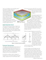
The use of a breakdown pad considerably reducesthe breakdown voltage sensitivity to surface states. Chip surface voltage control will still be required, but the chances of premature surface breakdown are now considerably reduced. Figure 7 shows a typical TISP base junction of transistor TR2. The current path isthrough transistor TR2, and resistor RH.The current levels are very low during this condition as shown in Figure 6.The breakdown region initiateswhen the applied voltage is sufficient to cause the diode D1,to avalanche. As the diode D1 isintegrated with transistor TR2, thebreakdown region...
Open the catalog to page 5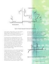
Switching Quadrant Blocking Quadrant > TR2TR1 On State Breakdown RHD1TR2TR1 Switch OffSwitch On > RHD1TR2 RHTR2TR1 RHD1TR2 -v-i +i + v Off StateBlocking > RHTR2 Figure 9. Protector Equivalent Circuits and VI characteristic > Figure 10. Reverse Blocking Unidirectional Thyristor > OCTOBER 2000 - REVISED AUGUST 2001 7 size="-1">
Open the catalog to page 6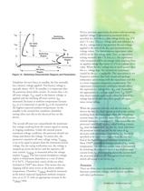
I > TSP SwitchingCharacteristic +v +iV I > TSM On-stateRegion I > T (BO) V > T SwitchingRegion I I > (BO) H BreakdownRegion I > DRM I > D V > D V > DRM -i Off-stateRegion > OCTOBER 2000 - REVISED AUGUST 2001
Open the catalog to page 8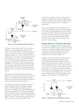
non-adjacent electrode connection to the gate. Inaddition to complimentary SCRs, this bidirectional function is given by a device called a TRIAC (Triode for Ac Control), which is used in 50 Hz/60 Hz applications.In the current-triggered mode, the SCRs providecurrent limiting to the protected load. By incorporat- ing a defined voltage breakdown region in the SCR structures, the SCRs will limit the maximum voltage to the load as well, by operating as fixed voltage protectors. When operating in the fixed voltage mode, the current from the protected load is not needed to cause switching. > +iv GA...
Open the catalog to page 13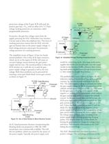
+ -v > G +i > G v - > GK Figure 18. Simplified Voltage Tracking Protection Circuit > OCTOBER 2000 - REVISED AUGUST 2001 size="-3">
Open the catalog to page 14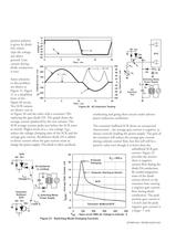
V > G V D4Th1 > K Voltage - V SLIC -60-50-40-30-20-10010 I I > G Time - ms05101520 > K R > AC V K I > K I > G = +80 mA > Bat V AC D2 I C2D3V > G = zero > Switching ModePower SupplyD1Tx V G ACInductionTest I > K IG - Gate Current - mA IK - Cathode Current - mA -80-60-40-2002040 6080100 C1 -300-200 -1000100200300 -100 Time - ms05101520 > IG(AV) - Average Gate Current - mA G(AV) G OCTOBER 2000 - REVISED AUGUST 2001 size="-1">
Open the catalog to page 15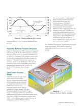
Transistor Buffered = +1.6 mA > G Transistor Buffered = -7 mAI I > G I > IG - Gate Current - mA IK - Cathode Current - mA K -300-200-1000100200300 -100-80-60-40-20020406080100 Time - ms05101520 > OCTOBER 2000 - REVISED AUGUST 2001 size="-1">
Open the catalog to page 16All BOURNS catalogs and technical brochures
 SM91501ALO BMS Transformer
4 Pages
 SM91502ALA BMS Transformer
4 Pages
 1.5SMBJ TVS Diode Series
6 Pages
 CG0402MLU/ CG0603MLU
3 Pages
 CG0402MLE/ CG0603MLE
3 Pages
 CG0402MLD/ CG0603MLD
3 Pages
 CG0402MLC/ CG0603MLC
3 Pages
 CG0402MLA/ CG0603MLA
4 Pages
 CG0603
1 Page
 CG0201MLA
1 Page
 CGA0603MLC
1 Page
 CGA0402MLC
1 Page
 CGA1206MLA
2 Pages
 CGA0805MLA
2 Pages
 CGA0603MLA
2 Pages
 Automotive Product Profile
12 Pages
 Industrial Panel Controls
8 Pages
 Sensors and Controls
73 Pages
 Bourns® Outside Plant Products
16 Pages
 Spotlight I
2 Pages
 Circuit Protection Selection Guide
108 Pages
 Trimpot® Product
172 Pages
 EMS22
EMS228 Pages
 EM14
EM148 Pages
 Pro Audio
12 Pages
 Rotary Encoders
8 Pages
 Resistor Networks
10 Pages
 Gas Discharge Tubes
16 Pages
 Fixed Resistors & Arrays
8 Pages
 Bourns Power Resistors
6 Pages
 Bourns RF Power Resistors
6 Pages
 ChipGuard®
6 Pages
 Chip Resistors & Arrays
8 Pages
 Diode
Diode16 Pages
 Bourns Product Profile
36 Pages
 Magnetic Encoders EMS22A
4 Pages
 Contacting Encoders 3315
5 Pages


Archived catalogs
 Trimpot® Product Catalog
172 Pages
 HFC Networks
3 Pages
 J.W. Miller Magnetics Catalog
204 Pages
 Inductive Component Solutions Guide
212 Pages
 Circuit Protection Selection Guide
108 Pages
 The Potentiometer Handbook
227 Pages
 Bourns® Product Profile Brochure
30 Pages


- Transformer
- Angular encoder
- Dry transformer
- Surge protector
- Incremental encoder
- Incremental rotary encoder
- Absolute rotary encoder
- IEC transformer
- Encapsulated transformer
- Power transformer
- Industrial rotary encoder
- Isolation transformer
- DC rotary encoder
- IP67 rotary encoder
- Compact rotary encoder
- Type 1 surge protector
- Potentiometer
- RoHS transformer
- Wire-wound resistor
- Manual potentiometer