HFC Networks

HFC Networks
Catalog excerpts

The Design Challenge: The continued development of new broadband services such as video and interactive programming is causing an ever-increasing demand for wider band- width. This quest for bandwidth has been responsible for the telecommunications industryΒs major step from copper based cabling to fiber optics. As fiber optics integrate themselves into most cable networks, they have now taken on a hybrid fiber/coax (HFC) style of architecture. HFC architecture has now become the leading choice of both Cable TV (CATV) companies and telephone service providers. Because of the similar- ity of the HFC architecture to their existing networks, cable companies in particular are embracing HFC as an affordable way to position themselves as telephony vendors in a competitive, multi- service future. CATV systems have a vision of providing a complete networked home package where video on demand (VOD), high speed internet and telephony will all be provided via one system: the HFC network. HFC Architecture: HFC architecture usually consists of a fiber trunk line carrying signals in the form of video or telephony from the headend or central office (CO), to feeder cables serving local neighborhoods. Optical nodes on the trunk line convert the signals from light in the fiber optics to radio frequencies (RF) for the copper cables. The feeder cable, a medium sized coaxial cable, provides the signals from the trunk cable to entire neighborhoods. Individual houses subscribing to the cable services have drop lines connected to the feeder cables via taps and network interface devices (NIDs) attached to the outside of their homes for cable telephony and set top boxes for video. Figure 1 below gives a basic layout of how an HFC network should look. > R1220T705 R1220T505 NIDDrop R1220T505 Node HeadendorCOFeeder Coax CableFiber TrunkCable Tap Figure 1. Hybrid fiber / coax (HFC) architecture Cable Telephony: Unlike cable TV where power to operate the TV is not transmitted along the cables, cable telephony requires applications power to operate the NIDs. In a cable telephony system, the cable transmits the signal information and in many cases the local operating power for the NIDs, in 60V to 90V form. Powering the local NID can be carried out in any of the following ways: >
Open the catalog to page 1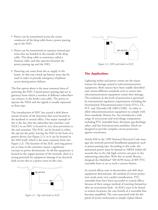
Power can be transmitted across the center conductor of the drop cable from a power passing tap to the NID.ՕPower can be transmitted on separate twisted pair wires that are bonded to the outside of the drop cable. This drop cable is sometimes called a Siamese cable, and also operates between the power passing tap and the NID.Powering can come from the ac supply in the home. In this case a back-up battery must also be used in order to provide emergency telephone access during power failures.The first option above is the most common form ofpoweringthe NID. Coaxial power passing taps act as gateways...
Open the catalog to page 2
Ю Asia-Pacific: TEL +886- (0)2 25624117FAX +886- (0)2 25624116 Europe: TEL +41-41 7685555FAX +41-41 7685510 North America: TEL +1-909 781-5500FAX +1-909 781-5700 bourns.com > COPYRIGHT Ω 2002, BOURNS, INC. LITHO IN U.S.A. 01/02 MF0182 rev size="-1">
Open the catalog to page 3All BOURNS catalogs and technical brochures
 SM91501ALO BMS Transformer
4 Pages
 SM91502ALA BMS Transformer
4 Pages
 1.5SMBJ TVS Diode Series
6 Pages
 CG0402MLU/ CG0603MLU
3 Pages
 CG0402MLE/ CG0603MLE
3 Pages
 CG0402MLD/ CG0603MLD
3 Pages
 CG0402MLC/ CG0603MLC
3 Pages
 CG0402MLA/ CG0603MLA
4 Pages
 CG0603
1 Page
 CG0201MLA
1 Page
 CGA0603MLC
1 Page
 CGA0402MLC
1 Page
 CGA1206MLA
2 Pages
 CGA0805MLA
2 Pages
 CGA0603MLA
2 Pages
 Automotive Product Profile
12 Pages
 Industrial Panel Controls
8 Pages
 Sensors and Controls
73 Pages
 Bourns® Outside Plant Products
16 Pages
 Spotlight I
2 Pages
 Circuit Protection Selection Guide
108 Pages
 Trimpot® Product
172 Pages
 EMS22
EMS228 Pages
 EM14
EM148 Pages
 Pro Audio
12 Pages
 Rotary Encoders
8 Pages
 Resistor Networks
10 Pages
 Gas Discharge Tubes
16 Pages
 Fixed Resistors & Arrays
8 Pages
 Bourns Power Resistors
6 Pages
 Bourns RF Power Resistors
6 Pages
 ChipGuard®
6 Pages
 Chip Resistors & Arrays
8 Pages
 Diode
Diode16 Pages
 Bourns Product Profile
36 Pages
 Magnetic Encoders EMS22A
4 Pages
 Contacting Encoders 3315
5 Pages


Archived catalogs
 Trimpot® Product Catalog
172 Pages
 J.W. Miller Magnetics Catalog
204 Pages
 Inductive Component Solutions Guide
212 Pages
 Circuit Protection Selection Guide
108 Pages
 The Potentiometer Handbook
227 Pages
 Bourns® Product Profile Brochure
30 Pages


- Transformer
- Angular encoder
- Dry transformer
- Surge protector
- Incremental encoder
- Incremental rotary encoder
- Absolute rotary encoder
- Encapsulated transformer
- Isolation transformer
- IP67 rotary encoder
- DC rotary encoder
- Type 1 surge protector
- Potentiometer
- RoHS transformer
- Manual potentiometer
- Type 3 surge arrester
- Rotary potentiometer
- 5VDC rotary encoder
- Analog potentiometer
- Primary transformer