Fluoractor® Fluorescent Lamp Starter Switch Y1112
1 /2Pages

Fluoractor® Fluorescent Lamp Starter Switch Y1112
1 /2Pages
Catalog excerpts
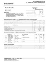
THE FLUORACTOR Y1112 FLUORESCENT LAMP STARTER SWITCH .. 1 JUNE 1984 - REVISED SEPTEMBER 2002 Specifications are subject to change without notice. œ V(BR) 1200 to 1500 V œ IH > 175 mA œ IGT < 2 mA description This product is intended for use as a T8/T12 fluorescent tube starter switch on 200-240 V a.c. supplies with tube sizes up to 5ft with leading and lagging ballast circuits. K A G TO-220 PACKAGE (TOP VIEW) Pin 2 is in electrical contact with the mounting base. MDC1ACA 1 2 3 absolute maximum ratings at 25°C case temperature (unless otherwise noted) RATING SYMBOL VALUE UNIT Crest working off-state voltage (Full wave rectified 50 Hz a.c.) VDWM 375 V Peak reverse gate voltage VRGM 6 V On-state current — continuous — repetitive peak — non-repetitive peak IT ITRM ITSM 1.5 2 10 A Peak gate current IGRM 0.5 A Average gate power PG(av) 0.3 W Operating case temperature range TC -5 to +85 °C Storage temperature range Tstg -10 to +110 °C Lead temperature during soldering 1.6 mm from the case for 10 seconds Tlead 230 °C electrical characteristics at 25°C case temperature (unless otherwise noted ) PARAMETER TEST CONDITIONS MIN TYP MAX UNIT ID Off-state current VD = VDWM Tj = 65°C 1 mA VT On-state voltage IT = 2 A 3.1 V V(BR) Clamping voltage IBR = 5 mA tp < 200 ìs, 2% duty cycle 1200 1500 V IH Holding current See application circuit 175 mA IGTM Peak gate trigger current VAA = 10 V RL = 10 Ù 2 mA VGTM Peak gate trigger voltage VAA = 10 V RL = 10 Ù 3 V thermal characteristics PARAMETER MIN TYP MAX UNIT RèJA Junction to free air thermal resistance 62.5 °C/W RèJC Junction to case thermal resistance 3.5 °C/W
Open the catalog to page 1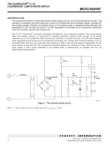
THE FLUORACTOR Y1112 FLUORESCENT LAMP STARTER SWITCH 2 .. JUNE 1984 - REVISED SEPTEMBER 2002 Specifications are subject to change without notice. applications data The conventional method of starting fluorescent tubes employs the use of an electromechanical canister. This consists of a bimetallic strip which opens as it cools and in conjunction with the ballast inductor, provides the tube striking voltage. However, the random nature of the pulsing results in repeated striking attempts and degradation of both the tube and starter. The tube degradation is illustrated by its progressively blackening...
Open the catalog to page 2All BOURNS catalogs and technical brochures
 SM91501ALO BMS Transformer
4 Pages
 SM91502ALA BMS Transformer
4 Pages
 1.5SMBJ TVS Diode Series
6 Pages
 CG0402MLU/ CG0603MLU
3 Pages
 CG0402MLE/ CG0603MLE
3 Pages
 CG0402MLD/ CG0603MLD
3 Pages
 CG0402MLC/ CG0603MLC
3 Pages
 CG0402MLA/ CG0603MLA
4 Pages
 CG0603
1 Page
 CG0201MLA
1 Page
 CGA0603MLC
1 Page
 CGA0402MLC
1 Page
 CGA1206MLA
2 Pages
 CGA0805MLA
2 Pages
 CGA0603MLA
2 Pages
 Automotive Product Profile
12 Pages
 Industrial Panel Controls
8 Pages
 Sensors and Controls
73 Pages
 Bourns® Outside Plant Products
16 Pages
 Spotlight I
2 Pages
 Circuit Protection Selection Guide
108 Pages
 Trimpot® Product
172 Pages
 EMS22
EMS228 Pages
 EM14
EM148 Pages
 Pro Audio
12 Pages
 Rotary Encoders
8 Pages
 Resistor Networks
10 Pages
 Gas Discharge Tubes
16 Pages
 Fixed Resistors & Arrays
8 Pages
 Bourns Power Resistors
6 Pages
 Bourns RF Power Resistors
6 Pages
 ChipGuard®
6 Pages
 Chip Resistors & Arrays
8 Pages
 Diode
Diode16 Pages
 Bourns Product Profile
36 Pages
 Magnetic Encoders EMS22A
4 Pages
 Contacting Encoders 3315
5 Pages


Archived catalogs
 Trimpot® Product Catalog
172 Pages
 HFC Networks
3 Pages
 J.W. Miller Magnetics Catalog
204 Pages
 Inductive Component Solutions Guide
212 Pages
 Circuit Protection Selection Guide
108 Pages
 The Potentiometer Handbook
227 Pages
 Bourns® Product Profile Brochure
30 Pages


- Transformer
- Angular encoder
- Dry transformer
- Surge protector
- Incremental encoder
- Incremental rotary encoder
- Absolute rotary encoder
- Encapsulated transformer
- Isolation transformer
- IP67 rotary encoder
- DC rotary encoder
- Type 1 surge protector
- Potentiometer
- RoHS transformer
- Manual potentiometer
- Type 3 surge arrester
- Rotary potentiometer
- 5VDC rotary encoder
- Analog potentiometer
- Primary transformer