
- Catalogs
- Boston Gear
- Series 2000R Right Angle Helical Bevel Gear Drives & Gear Motors

Series 2000R Right Angle Helical Bevel Gear Drives & Gear Motors

Series 2000R Right Angle Helical Bevel Gear Drives & Gear Motors
The document introduces the Series 2000R Right Angle Helical Bevel Gear Drives and Gear Motors by Boston Gear, part of Altra Industrial Motion. This series includes stainless steel options for harsh washdown applications, suitable for industries such as food processing and material handling.
- Performance: High torque with AGMA standard ratings, tested for 25,000 hours.
- Design Flexibility: Offers various shaft options and input styles, including NEMA and IEC C-FACE motor mounts.
- Installation: Features quick and precise alignment with unique mounting registers and keyless tapered bushing.
- Maintenance: Includes automatic wear debris entrapment, corrosion-resistant paint, and synthetic lubrication for extended gear life.
Suitable for cheese slicers, dairy mixers, meat processing, bottling lines, and conveyors.
With 98% efficiency per gear mesh, these gear drives are ideal for continuous operations and high-ratio reductions.
Provides detailed ordering codes for various configurations, including bore sizes, mounting positions, and motor types.
Includes data on input horsepower, output speed, torque ratings, and safety factors for different models and configurations.
Boston Gear's Series 2000R offers robust, flexible, and efficient solutions for industrial applications, supported by extensive engineering expertise and industry experience.
Outlines various assembly types and components, including kits with parts such as N1, K1, L1, J1, and key sizes like H1, Ø G1, and Ø M1. Provides specific part numbers and measurements in both inches and millimeters.
Lists installation hardware kits with part numbers corresponding to different assembly types, with dimensions in both inches and millimeters.
Provides specifications for torque arms, including size, degrees of rotation, and specific lengths, along with mounting details and shipping condition notes.
Includes instructions for mounting registers and tapered adaptors to ensure proper alignment between the reducer output shaft and the driven shaft.
Discusses various paint options like Two-Tuff Bost-Kleen™ and Stainless Bost-Kleen™, each with specific characteristics and USDA approvals, along with installation aids for easier setup.
Recommends Klubersynth GH6-460 for lubrication, with details on operating temperatures and relubrication intervals, including a table for lubricant specifications and mounting positions.
Provides contact details for various product lines and services, including phone numbers and locations for customer service and application assistance.
Catalog excerpts
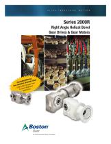
Series 2000R Right Angle Helical Bevel Gear Drives & Gear Motors ing Offer eel nded inless St pa Ex ta Steel des S Inclu R Stainless ow 000 down SSRF2 arsh Wash H for ations Applic
Open the catalog to page 1
Altra Industrial Motion Boston Gear This well recognized Altra Industrial Motion brand has utilized its gearing expertise to offer the innovative Series 2000 product line. Boston Gear products have a reputation for superior engineering, quality manufacturing and reliable performance. As an industry leader, we have extensive experience and application knowledge in industries including material handling, food processing, packaging, bottling, and metals. For more information about Series 2000 Gear Drives or Gear Motors call: 888-243-3447 Series 2000R Right Angle Helical Bevel Gear Drives and Gear...
Open the catalog to page 2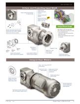
C-Face and Projecting Input Shaft Unique rounded housing surfaces for easier cleaning Unique Two-Tuff premium acrylic paint (standard) Washdown epoxy paint (optional) Stainless Steel Housing NE (optional for sizes 2043R & 2063R C-Face only) Energy Efficient Design With efficiency of 98% per gear mesh, Series 2000 helical bevel reducers are ideal for use in applications with: - continuous or high duty cycle operations - high-ratio reduction - limited access applications where long life is a necessity Optional unique keyless tapered bushing provides longer life and faster installation Stainless...
Open the catalog to page 3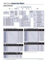
Ordering Information Example: GH1-2043RF35WG1P22 GH 1 - 2043R F 35 W G 1 Exterior Blank Two-Tuff GE Integral Gear Motor - 1/3 HP GF Integral Gear Motor - 1/2 HP GG Integral Gear Motor - 3/4 HP GH Integral Gear Motor - 1 HP GJ Integral Gear Motor - 1.5 HP GK Integral Gear Motor - 2 HP GL Integral Gear Motor - 3 HP GM Integral Gear Motor - 5 HP GN Integral Gear Motor - 7.5 HP GP Integral Gear Motor - 10 HP GR Integral Gear Motor - 15 HP Chart 1: Hollow Bore Codes - Inch Sizes s = standard •=Optional Nominal Bore Diameter Nominal Bore Nominal Bore Diameter (mm) Bore Code Decimal Size Chart...
Open the catalog to page 4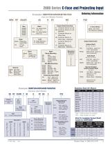
Example: SBKRF2043R40KB7HS1P22 Ordering Information Cast Iron Models (Painted) SBK RF 2043R 40 K B7 HS 1 P22 T C-Face Motor Blank No motor Per Reducer catalog Base Blank None T Torque Arm Exterior Blank Two-Tuff BK Bost-Kleen SBK Stainless Bost-Kleen Mounting Positions See page 21 Output Shaft Code Hollow Shaft See Chart 1 or Chart 2 P24 Inch Bore - spec'd in 1/16" increments PM40 Metric Bore- spec'd in mm increments Solid Shaft See Chart 4 or Chart 5 D20 Inch OD - spec'd in 1/16" increments DM25 Metric OD - spec'd in mm increments Tapered Adaptor Hollow Output Shaft See...
Open the catalog to page 5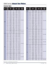
Selection Tables Output Input Speed HP (1750 rpm Input) Actual Ratio Output Torque Rating (lbf-in) Safety Factor Ratio Model Ratings Based on AGMA Standards (using GH6-460 oil)
Open the catalog to page 6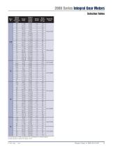
Consult Factory for Ratio and Motor HP combinations not shown above. Consult Factory for Motor HP above 15 HP.
Open the catalog to page 9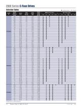
2000 Series C-Face Drives Selection Tables Output Speed (1750 rpm Input) n Available Options Actual Ratio Ratio used in Part No. Output Torque Rating (lbf-in) NEMA C-Face Input B5 Ratings based on AGMA Standards
Open the catalog to page 10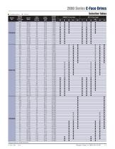
2000 Series C-Face Drives n Available Options Model No. Selection Tables Output Speed (1750 rpm Input) Actual Ratio Ratio used in Part No. Output Torque Rating (lbf-in) NEMA C-Face Input B5 Ratings based on AGMA Standards P-7077-BG
Open the catalog to page 11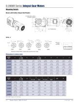
T Threaded Holes on 0 BC1 (as shown in Detail A) DETAIL A Side shown matches DETAIL A. Opposite side would have mirror image. Note: Refer to page 18 for shaft detail.
Open the catalog to page 12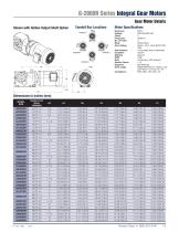
Enclosure Voltage Phase Frequency No. of Poles Body Encl. Rating Seal features Insulation Winding RPM Duty Service Factor Supports Drive usage Compliance Shown with Hollow Output Shaft OptionMotor Specifications TEFC 208-230/460 VAC 3 50/60 Hz 4 Rolled Steel Class I, Div 2, Grps B/C/D/T3C IP55 V-ring seals (both endshields) Class F Class B 1800 Continuous, 40C ambient 1.15 Ball bearings NEMA MGI Part 31 rated for use with VFD 2:1 CT and 10:1 VT EISA 2007, UR, CSA, CE
Open the catalog to page 13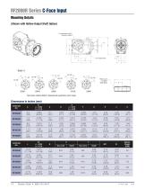
T Threaded Holes on 0 BC1 (as shown in Detail A)_ Detail A Refer to p.20 -for Hollow Shaft Details Side shown matches Detail A. Opposite side would have mirror image. Approx. Weight (LBS)
Open the catalog to page 14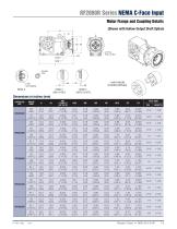
Motor Flange and Coupling Details (Shown with Hollow Output Shaft Option) CATALOG INPUT NO. SIZE
Open the catalog to page 15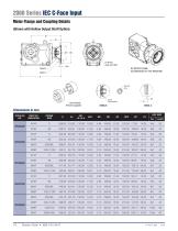
IEC MO TOR FLANGE ACCOMODATES B5-TYPE MOUNTING FRAME SIZE
Open the catalog to page 16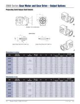
ASSEMBLY TYPE G SHOWN ABOVE SHAFT STYLES SINGLE PROJECTING OUTPUT SHAFT (G/J) DOUBLE PROJECTING OUTPUT SHAFT (H) Dimensions in inches SIZE
Open the catalog to page 18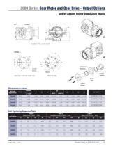
ASSEMBLY TYPE J SHOWN ABOVE Dimensions in inches PART NO. Bolt Tightening Sequence Table PART NO. IDENTIFIER S1 Initial Torque - ft.lbs. Apply Secondary Torque - ft.lbs. STEP 3 Apply Final Torque - ft.lbs. S1 S2 S3 S4
Open the catalog to page 19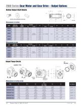
INSTALLATION HARDWARE (SUPPLIED) FULL LENGTH FULL LENGTH Output Flange Details Dimensions in inches (mm) SIZE
Open the catalog to page 20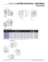
T...J Dimensions in inches SIZE
Open the catalog to page 21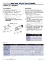
Mounting Registers Mounting Registers on the 2000 Series products enable a simpler installation for Base Mounted units. Use the following steps to assist in the alignment between the reducer output shaft and the shaft being driven (driven shaft). 1. Establish a reference edge that is parallel to the driven shaft using dimension M as the offset. 2. Bank Reference Face 3 of the reducer against your reference edge. 3. Use Reference Face 2 of the reducer for any fine angular (yaw) or lateral adjustments. Contacting thumbscrews against Reference Face 2 is a clever method. MOUNTING REGISTERS Tapered...
Open the catalog to page 22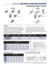
Lubrication Klubersynth GH6-460 that is recommended for the 2000 Series gear drives for optimum performance. Normal full-load operating temperatures range between 130F - 150F. During initial break-in of the gear drive, higher than normal operating temperatures may result. All gear drives are supplied with GH6-460 synthetic oil (unless specified otherwise) with quantity listed below for standard mounting position 1 or to mounting specified at time of order. These gear drives are designed with internal features to reduce the impact of metallic wear debris, which should increase maintenance intervals....
Open the catalog to page 23All Boston Gear catalogs and technical brochures
 Rotary Drive Products
340 Pages
 p-1483-bg
97 Pages
 Electrical Products Catalog
130 Pages
 Enclosed Gear Drives
368 Pages
 Rotary Drives
340 Pages
 Centric Centrifugal Clutches
2 Pages
 Gearhead Catalog
40 Pages
 Centric Overload Clutches
108 Pages
 2000 series
28 Pages
 2000R
2000R24 Pages
 Centric Centrifugal Flyer
2 Pages
 Centrigard Overload Clutch
2 Pages


Archived catalogs
 Gear Catalog
172 Pages
 Huco Air Motors
28 Pages
 Huco Precision Couplings
60 Pages
 Bearing Products Catalog
224 Pages
- Power transmission belt
- Steel bearing
- Right angle gearhead
- Compact gearhead
- Flexible coupling
- Ball bearing
- Gear train gear reducer
- Radial bearing
- Gearbox for industrial applications
- Transmission gearhead
- Rubber strip
- Helical gear gearhead
- Machines gearbox
- Flange coupling
- Pneumatic motor
- High-torque gearhead
- Bevel gearhead
- Modular gearhead
- Vane air motor