video corpo
cad

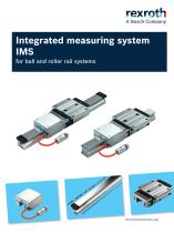
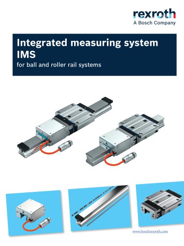
Integrated measuring system IMS

Integrated measuring system IMS
1 / 78 PagesView full catalog

Integrated measuring system IMS

Product catalog summary
Overview: The document provides a comprehensive overview of the Integrated Measuring System (IMS) for ball and roller rail systems by Bosch Rexroth. It highlights new features, technical specifications, and the benefits of integrating measuring technology into linear guides.
New Features: The IMS-A now supports modular, multi-part guide rails, allowing configurations for rail tracks longer than 4500 mm. It also introduces interfaces like DRIVE-CLiQ® and BiSS-C for transmitting acceleration data, enhancing machine functions such as condition monitoring.
Product Description: The IMS integrates measuring technology into linear guides, eliminating the need for external systems. It offers both absolute and incremental measuring systems, with features like contactless measurement, high precision, and resistance to environmental factors.
Technical Specifications: The document details technical data for various components, including runner blocks, guide rails, and scanners. It emphasizes the system's precision, with repeatability of ±0.25 μm and position resolution of 0.025 µm.
Advantages: The IMS offers space and cost savings, improved machine dynamics, and maintenance-free operation. It supports new machine functions like vibration analysis and process monitoring, with acceleration data available without additional wiring.
Structural Design and Integration: The IMS is fully integrated into the guide system, requiring no additional installation space or mounting surfaces. It simplifies machine design and reduces installation and commissioning time.
Applications: The system is suitable for various applications, including those with shocks or vibrations, and is resistant to magnetic fields, water, oil, and dust.
Conclusion: The IMS by Bosch Rexroth enhances machine performance and reliability through its integrated design, precision, and advanced features, offering significant benefits throughout the machine's lifecycle.
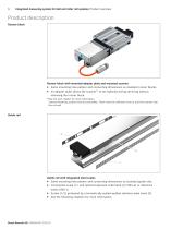
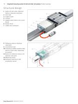
Structural Design: The IMS consists of several components including a guide rail with scale, reference marks or absolute code band, a front seal, support plate, scanner, adapter plate, runner block, and cables. The scanner is a critical component that houses the contactless, inductive scanning system for incremental or absolute measuring functions.
Technical Specifications: The document outlines the forces and moments acting on the runner block, emphasizing the need for precise load calculations. It provides detailed technical data for the scanner, including its mounting, signal processing electronics, and interface circuitry. The IMS supports various interfaces such as HIPERFACE®, BiSS-C, SSI, and DRIVE-CLiQ, each with specific voltage supply, current consumption, and resolution parameters.
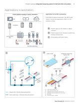
Applications in Automation: The IMS is primarily used in sensor-level applications within industrial automation, enhancing positioning accuracy in linear motor axes and drive systems. It supports closed-loop and semi-closed loop control circuits, improving the control platform topology in factory automation.
Key Features: The IMS includes evaluation electronics with an integrated MEMS acceleration sensor, enabling extended condition monitoring functions. It also features a robust design with protection against environmental factors, ensuring reliable operation in industrial settings.
Recommendations: The document advises on the structural design considerations, such as specifying the push-on direction of the IMS runner block and ensuring the cable outlet aligns with the incremental scale. It also highlights the importance of adhering to specified load values for optimal performance.
Connector Specifications: The document outlines various connector types used in ball and roller rail systems, specifying their protection class (IP67 when locked) and pin configurations. Key connectors include M17 with 17 pins, M12 with 8 pins, and M23 with 17 pins, each serving different functions such as voltage supply, data transmission, and signal processing.
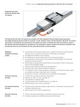
Guide Rail Description: The guide rail integrates an incremental scale and reference marks or an absolute code band, eliminating the need for additional assembly. The rail is protected by a stainless-steel cover, achieving protection class IP67. The document specifies that braking or clamping elements should not be used in the area of the integrated scale.
Modular IMS-A Guide Rails: These guide rails allow for multi-part rail tracks with up to eight sections. They are available with or without measuring functions and must be marked to avoid confusion with standard rails. The document provides order options for modular configurations.
System Accuracy and Thermal Behavior: The document details the accuracy of the measuring system, including position deviations and accuracy classes. It also discusses the thermal behavior of the IMS, highlighting the influence of the mounting base on longitudinal expansion.
Lubrication and Maintenance: Ball and roller rail systems are delivered with anti-corrosion agents and require initial lubrication before commissioning. Lubrication is facilitated via free lube fittings.
Ball Runner Blocks: The document provides a comprehensive overview of ball runner blocks, including available versions, type designations, and technical data. It specifies characteristics such as preload class, accuracy class, seal type, and interface options.
Ball Guide Rails: Ball guide rails are available with cover strips and protective caps or plastic caps, each with integrated scales. The document lists available sizes and versions, along with their dimensions. It highlights the importance of securing cover strips and provides guidance on mounting instructions.
Roller Runner Blocks: Specifications for roller runner blocks include size, preload class, accuracy class, and seal type. The document provides detailed dimensions and permissible load values for each size. It also outlines the delivery components, including mounted adapter plates and scanners, and emphasizes following mounting instructions.
Technical Data and Recommendations: The document includes tables with technical data for each component, specifying dimensions, load capacities, and other critical parameters. It advises on maintaining minimum distances between reference marks and securing components properly. The document also provides ordering examples and references additional chapters for comprehensive instructions.
Specifications: The document details specifications for various cables and integrated measuring systems (IMS) used in ball and roller rail systems. Key specifications include cable types, compliance with RoHS and AWM standards, cable dimensions, and bending capabilities. Maximum cable lengths are specified for different interfaces, with considerations for connectors and EMC behavior.
Procedures: Instructions for mounting and maintaining the measuring systems are provided, emphasizing careful handling. Detailed instructions are available in referenced documents for mechanical and electrical interfaces.
Standards and Directives: The document outlines compliance with several directives and standards, including DIN EN ISO 12100, Directive 2006/42/EC, and REACH Regulation (EC) No. 1907/2006. These standards cover safety, health requirements, and restrictions on dangerous substances.
Recommendations: Recommendations are made for using specific cables and connectors for different IMS interfaces, such as DRIVE-CLiQ and FANUC. The document advises on the intended use of rail systems and warns against misuse, which includes using the product in hazardous environments or for unintended purposes.
Safety Instructions: Safety instructions emphasize compliance with local safety regulations and maintaining the product in perfect condition. The document warns against unauthorized modifications and highlights the importance of adhering to technical data and environmental conditions.
Ordering Information: Detailed ordering examples for roller rail systems and guide rails are provided, specifying characteristics such as size, design, preload class, and accuracy class.
Additional Information: The document includes contact information for Bosch Rexroth AG and notes on the natural wear and aging of products.
See more

Catalog excerpts

Integrated measuring system IMS-1

Integrated measuring system IMS for ball and roller rail systems

 Open the catalog to page 1

Integrated measuring system IMS-2

Integrated measuring system for ball and roller rail systems  New features at a glance Modular, multi-part guide rails for IMS-A The possibility of modular joints allows multi-part IMS-A rails to be configured very easily. This makes it possible to create rail tracks > 4500 mm (Page 24). IMS-A interface DRIVE-CLiQ® with acceleration data With the new ordering option "D4," in addition to the position data, acceleration data from the integrated MEMS sensor in the X/Y/Z direction can be cyclically read out and transmitted to SIEMENS controllers. This makes it possible to implement fundamentally...

 Open the catalog to page 2
Integrated measuring system IMS-3

Integrated measuring system for ball and roller rail systems General technical data and calculations for runner block 11 Description and technical data of scanner (IMS-I / IMS-A) 12 Description and technical data of scanner (IMS-I) 14 Description and technical data of scanner (IMS-A) 16 Description and technical data of connectors and cables 20 Description and technical data of guide rail 24 Description and technical data of the overall system 28 Ball runner blocks - Technical data and dimension drawings 32 Product overview and type designations for ball runner blocks 32 Ball runner block FNS...

 Open the catalog to page 3
Integrated measuring system IMS-4

Integrated measuring system for ball and roller rail systems! Product overview IMS - Integrated measuring system: absolute/incremental - inductive - precise - integrated

 Open the catalog to page 4
Integrated measuring system IMS-5

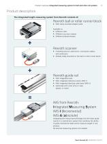
Product overview | Integrated measuring system for ball and roller rail systems The integrated length measuring system from Rexroth consists of: Rexroth ball or roller runner block ► With ready-mounted adapter plate ► Different accuracy classes ► Different preload classes ► Including sensors, electronics, connection cables, and connectors ► Already ready-mounted on the ball or roller runner block ► With integrated scale ► With integrated reference marks (IMS-I) ► With integrated absolute code band (IMS-A) ► Optionally with cover strip or caps (plastic or steel) Integrating the measuring technology...

 Open the catalog to page 5
Integrated measuring system IMS-6

Integrated measuring system for ball and roller rail systems! Product overview Runner block Runner block with mounted adapter plate and mounted scanner ► Same mounting hole pattern and connecting dimensions as standard runner blocks. ► An adapter plate allows the scanner1 to be replaced during servicing without removing the runner block. 1) See the next chapter for more information. Scanner fastening screws must be accessible. There must be sufficient room to pull the scanner over the rail end. Guide rail Guide rail with integrated steel scales ► Same mounting hole pattern and connecting dimensions...

 Open the catalog to page 6
Integrated measuring system IMS-7

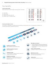
Integrated measuring system for ball and roller rail systems The Rexroth ball and roller rail systems are available with fully integrated inductive length measuring system. The length measuring system consists of a scanner, a scale, reference marks, and the absolute code band. The scanner with sensors is mounted on the runner block. As it travels over them, it evaluates the scale, the reference marks or the absolute code band integrated in the guide rail. This mechatronic system combines the functions of guidance and measurement into one unit and opens up new, ideal opportunities in machine design....

 Open the catalog to page 7
Integrated measuring system IMS-8

Integrated measuring system for ball and roller rail systems | Product overview  Your benefits Compact machine design 1 Space requirement for external length measuring system is eliminated 1. Linear guide 2. Linear encoder 3. Integrated measuring system IMS 4. Savings in terms of installation space From structural design to service The IMS offers a high degree of cost-effectiveness that extends over the entire life cycle. From engineering to installation and commissioning through to maintenance and service. High rigidity and robustness ▶ Simplified structural design Fewer components, less installation...

 Open the catalog to page 8
Integrated measuring system IMS-9

Product overview | Integrated measuring system for ball and roller rail systems 9 Applications in automation Applications for the IMS in automation: Control platform topology in factory automation In the field of industrial automation, the IMS is used mostly in sensor-level applications, that is, on I/O modules or drives. Position sensor at I/O modules or digital indicators Closed control circuit: Increase in positioning accuracy at linear axes Drive systems with linear motors MOTORS & ENCODER Linear motor Integrated measuring system IMS Target position 4 Linear motor axis 2 Closed loop / directly...

 Open the catalog to page 9
Integrated measuring system IMS-10

10 Integrated measuring system for ball and roller rail systems | Product overview 1 Guide rail with scale, reference marks or absolute code band 5 Adapter plate (fixed to the runner block) 8 Reference marks or absolute code band 10 Covered by welded stainless-steel band (on both sides, depending on version) 11 Sensor for reference marks or for absolute code band 13 Evaluation electronics with acceleration sensor

 Open the catalog to page 10
Integrated measuring system IMS-11

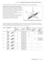
Technical data | Integrated measuring system for ball and roller rail systems 11 Loads due to forces and moments on the runner block The forces acting on the system are distributed among the runner blocks depending on the arrangement. The loads caused by forces and moments resulting from the effective forces need to be calculated for each runner block when performing the life expectancy calculation. All load calculations assume an infinitely rigid mounting base and an infinitely rigid structure. The life expectancy calculation for the IMS is analogous to the calculation of the life expectancy...

 Open the catalog to page 11
Integrated measuring system IMS-12

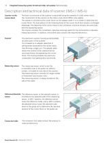
Integrated measuring system for ball and roller rail systems | Technical data  Description and technical data of scanner (IMS-I / IMS-A) Scanner on the The basic construction of the scanner is explained using the example of a ball runner block. runner block The construction of the scanner on the roller runner block differs only slightly. The scanner is secured to the runner block via the adapter plate. It is no wider or taller than the runner block. The hole pattern of the fastening bores of the runner block also remains unchanged. Advantage: The fastening of the runner block to the connection...

 Open the catalog to page 12

All Bosch Rexroth - Linear Motion Technology catalogs and technical brochures

  1. Screw assemblies

    284  Pages

*Prices are pre-tax. They exclude delivery charges and customs duties and do not include additional charges for installation or activation options. Prices are indicative only and may vary by country, with changes to the cost of raw materials and exchange rates.
About DirectIndustry
DirectIndustry is a marketplace that offers B2B players a complete experience, from product sourcing to purchase. DirectIndustry is an entity of VirtualExpo Group.