- Catalogs
- Bosch Rexroth - Linear Motion Technology
- Catalog Integrated Measuring System IMS for Ball and Roller Rail Systems
Catalog Integrated Measuring System IMS for Ball and Roller Rail Systems
1 /68Pages

Catalog Integrated Measuring System IMS for Ball and Roller Rail Systems
1 /68Pages
Catalog excerpts
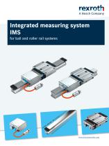
Integrated measuring system IMS for ball and roller rail systems
Open the catalog to page 1
Integrated measuring system for BRS and RRS |
Open the catalog to page 2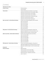
| Integrated measuring system for BRS and RRS 3 Contents New features at a glance Product overview Product description Structural design General technical data and calculations of runner blocks Technical data Description and technical data of scanner (IMS-I / IMS-A) Description and technical data of scanner (IMS-I) Description and technical data of scanner (IMS-A) Description and technical data of connectors and cable Description and technical data of guide rail Description and technical data of overall system Product overview and type designation, ball runner blocks Ball runner blocks FNS Ball...
Open the catalog to page 3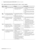
Integrated measuring system for BRS and RRS | New features at a glance IMS – Integrated measuring system: absolute/incremental – inductive – accurate - integrated Feature ▶▶ Absolute measuring system with absolute and incremental coded scales ▶▶ Absolute position information imme- ▶▶ Space-saving and cost advantage, since diately after switching on the system no additional components are required ▶▶ Absolute position information is (e.g., battery) stored directly in the rail ▶▶ Savings in time: Switch on without reference run minimizes ramp-up time of the machine ▶▶ Quality improvement: Avoiding...
Open the catalog to page 4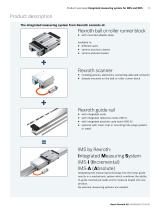
Product overview | Integrated measuring system for BRS and RRS 5 Product description The integrated measuring system from Rexroth consists of: Rexroth ball or roller runner block ▶▶ with mounted adapter plate available in: ▶▶ different sizes ▶▶ various accuracy classes ▶▶ various preload classes Rexroth scanner ▶▶ including sensors, electronics, connecting cable and connector ▶▶ already mounted on the ball or roller runner block Rexroth guide rail ▶▶ with integrated scale ▶▶ with integrated reference marks (IMS-I) ▶▶ with integrated absolute code band (IMS-A) ▶▶ optional with cover strip or mounting...
Open the catalog to page 5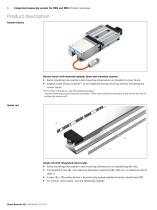
Integrated measuring system for BRS and RRS | Product overview Product description Runner blocks Runner block with mounted adapter plate and mounted scanner ▶▶ Same mounting hole pattern and mounting dimensions as standard runner block ▶▶ Adapter plate allows scanner1) to be replaced during servicing without removing the runner block. 1) For further information, see the following chapter. Scanner fastening screws must be accessible. There must sufficient clearance at the end of the rail for pulling the scanner off. Guide rail Guide rail with integrated steel scales ▶▶ Same mounting hole pattern...
Open the catalog to page 6
Product overview | Integrated measuring system for BRS and RRS 7 Integrated measuring system IMS for ball and roller rail systems Rexroth ball rail and roller rail systems can be supplied with a completely integrated, inductive linear measuring system. The length measuring system consists of a scanner, a scale, reference marks, and the absolute code band. The Scanner with sensors is mounted on the runner block. As it travels over them, it evaluates the scale, the reference marks or the absolute code band integrated in the rail. This mechatronic system combines the functions of guidance and measurement...
Open the catalog to page 7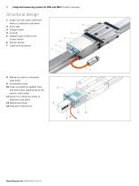
Integrated measuring system for BRS and RRS | Product overview Structural design 1 Guide rail with scale, reference marks or absolute code band 2 Front seal 3 Support plate 4 Scanner 5 Adapter plate (fixed to the runner block) 8 Reference marks or absolute code band 9 Incremental scale 10 Cover provided by welded stain- less-steel band (depending on the version, both sides) 11 Sensor for reference marks or absolute code band 12 Measuring sensor
Open the catalog to page 8
Technical data | Integrated measuring system for BRS and RRS 9 General technical data and calculations of runner blocks Loads due to forces and moments on the runner block The forces acting on the system are distributed among the guiding wagons depending on the runner block. The loads due to forces and torques resulting from the effective forces need to be calculated for each runner block when performing the life expectancy calculation. All load calculations require an infinitely rigid mounting base and an infinitely rigid structure. The service life calculation for the IMS is performed in a...
Open the catalog to page 9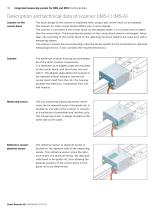
Integrated measuring system for BRS and RRS | Technical data Description and technical data of scanner (IMS-I / IMS-A) Scanner on the The basic design of the scanner is explained here, using a ball runner block as an example. runner block The scanner for roller runner blocks differs only in minor details. The scanner is mounted on the runner block via the adapter plate. It is no wider and no higher than the runner block. The mounting hole pattern of the runner block remains unchanged. Advantage: The mounting of the runner block on the adjoining structure remains the same even with a measuring...
Open the catalog to page 10
Technical data | Integrated measuring system for BRS and RRS 11 Evaluation electronics The evaluation electronics contains all components for generating, processing, calibrating and transmitting signals. These signals are evaluated by external electronics (e.g. IndraDrive servo controller from Rexroth). To provide added protection, a front seal (1) is screwed onto the scanner. This prevents water, oil, cooling lubricant, shavings and dust from working their way into the scanner from the end face. The bottom side of the scanner is protected by longitudinal seals (3). Support plate The support...
Open the catalog to page 11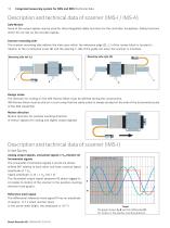
Integrated measuring system for BRS and RRS | Technical data Description and technical data of scanner (IMS-I / IMS-A) Safe-Motion None of the output signals may be used for drive-integrated safety functions for the controller. Exceptions: Safety functions which do not rely on the encoder signals. Scanner mounting side The scanner mounting side defines the side upon which the reference edge (2, ) of the runner block is located in relation to the incremental scale (1) and the spacing T1 (3) of the guide rail when the scanner is mounted. Mounting side right (R) Mounting side left (L) Design...
Open the catalog to page 12All Bosch Rexroth - Linear Motion Technology catalogs and technical brochures
 Roller rail systems_2022
206 Pages
 Smart Function Kit
28 Pages
 Screw assemblies
280 Pages
 Ball Transfer Units
36 Pages
 Linear Modules
164 Pages
 Electromechanical Cylinder EMC
60 Pages
 High-Speed Ball Rail Systems
16 Pages
 eLINE Compact Modules
72 Pages
 Cam Roller Guides
56 Pages
 eLINE Profiled Rail Systems
36 Pages
 Roller Rail Systems
168 Pages
 Integrated Measuring System
28 Pages
 Kugelschienenführungen
264 Pages
 Feed Modules VKK
48 Pages


Archived catalogs
 Roller Rail Systems82016
216 Pages