- Catalogs
- Bosch Rexroth - Industrial Hydraulics
- Hydraulic cylinders Tie rod design
Hydraulic cylinders Tie rod design
1 /92Pages

Hydraulic cylinders Tie rod design
1 /92Pages
Catalog excerpts
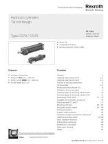
The Drive & Control Company Rexroth Bosch Group Hydraulic cylinders Tie rod design RE 17016 Edition: 2014-03 Replaces: 08.08 ► 16 types of mounting ► Piston 0 (0AL) 25 ... 200 mm ► Piston rod 0 (0MM) 12 ... 140 mm ► Stroke length up to 3 m Ordering code: Series CD70 2, 3 Ordering code: Series CG70 4, 5 Position of the line connections 6 Project planning software ICS 8 Diameters, forces and areas 9 Overview types of mounting: Series CD70 10 Overview types of mounting: Series CG70 11 Enlarged line connection 13 and 14 76 Admissible stroke lengths 82 ... 84 Support width extension 85 Installation lengths and position tolerances 86 Inductive proximity switch 87, 88 Seals (standard versions) 89 Braking force calculation 90 Spare parts drawing 91 Project planning software Interactive Catalog System Bosch Rexroth AG, RE 17016, edition: 2014-03
Open the catalog to page 1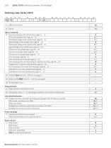
Bosch Rexroth AG, RE 17016, edition: 2014-03
Open the catalog to page 2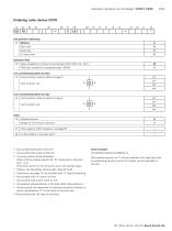
Hydraulic cylinders, tie rod design | CD70 / CG70 3/92 1) Not possible with piston 0 25 mm 2) Not possible with piston 0 200 mm 3) Trunnion position freely selectable. When ordering, always specify the "XV" dimension in the plain text in mm. With piston 0 25 mm, the trunnions are at the cylinder head. 4) Observe the admissible stroke length, page 82 to 84 5) Dimensions see page 76. Not possible with "K" type of mounting. 6) Not possible with "E" piston rod end 7) Not possible with piston rod 0 12 mm 8) All graphical representations in the data sheet show position 1 9) Always specify the attachment...
Open the catalog to page 3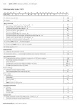
Bosch Rexroth AG, RE 17016, edition: 2014-03
Open the catalog to page 4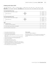
Hydraulic cylinders, tie rod design | CD70 / CG70 5/92 70 1X Line connection/position at head 14 Enter position; observe table on page 6! Line connection/position at base 15 Enter position; observe table on page 6! 17 Enter support width extension; see page 85 18 Further details in the plain text 8) 1) Not possible with piston 0 25 mm 2) Not possible with piston 0 200 mm 3) Trunnion position freely selectable. When ordering, always specify the "XV" dimension in the plain text in mm. With piston 0 25 mm, the trunnions are at the cylinder head. 4) Observe the admissible stroke length, page 82 to...
Open the catalog to page 5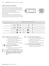
6/92 CD70 / CF70 | Hydraulic cylinders, tie rod design Position of the line connections By rotating the cylinder head and/or cylinder base, the position of the line connections can be varied during the assembly for most cylinder mounting types. The possibilities can be seen in the following table. Throttle and check valve will also change their position accordingly. With F, L, N and T types of mounting as well as at the cylinder base with G type of mounting, throttle and check valve are in position 1 when the line connection is rotated. Selectable position of the line connections Position 2 and...
Open the catalog to page 6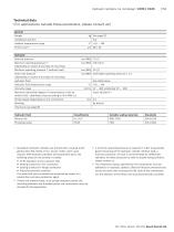
Hydraulic cylinders, tie rod design | CD70 / CG70 7/92 3) A minimum operating pressure is required in order to guarantee good functioning of the hydraulic cylinder. Without load, a minimum pressure of 10 bar is recommended for differential cylinders; for lower pressures as well as double-acting cylinders, please contact us. 4) The cleanliness classes specified for the components must be adhered to in hydraulic systems. Effective filtration prevents faults and at the same time increases the life cycle of the components. For the selection of the filters see www.boschrexroth.com/filter. RE 17016,...
Open the catalog to page 7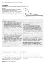
CD70 / CF70 | Hydraulic cylinders, tie rod design Life cycle: Rexroth hydraulic cylinders correspond to the reliability recommendations for industrial applications. ≥ 10000000 double strokes in idle continuous operation or 3000 km piston travel at 70 % of the nominal pressure, without load on the piston rod, with a maximum velocity of 0.5 m/s, with a failure rate of less than 5 %. Notice! Boundary and application conditions: ▶▶ The mechanical alignment of the movement axis and thus the mounting points of hydraulic cylinder and piston rod must be ensured. Lateral forces on the guides of piston...
Open the catalog to page 8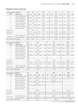
Hydraulic cylinders, tie rod design | CD70 / CG70 9/92 RE 17016, edition: 2014-03, Bosch Rexroth AG
Open the catalog to page 9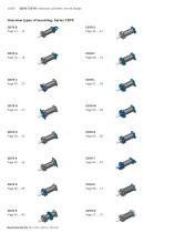
CD70 / CF70 | Hydraulic cylinders, tie rod design Overview types of mounting: Series CD70 CD70 B Bosch Rexroth AG, RE 17016, edition: 2014-03
Open the catalog to page 10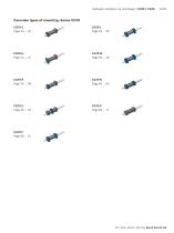
Hydraulic cylinders, tie rod design | CD70 / CG70 11/92 Overview types of mounting: Series CG70 CG70 C RE 17016, edition: 2014-03, Bosch Rexroth AG
Open the catalog to page 11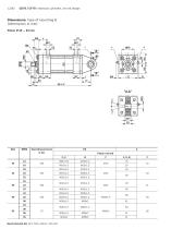
12/92 CD70 / CF70 | Hydraulic cylinders, tie rod design Dimensions: Type of mounting B (dimensions in mm) Piston 0 25 ... 63 mm Bosch Rexroth AG, RE 17016, edition: 2014-03
Open the catalog to page 12
Hydraulic cylinders, tie rod design | CD70 / CG70 13/92 0AL = Piston 0 0MM = Piston rod 0 X* = Stroke length 1) Raised cylinder head and base 2) Raised cylinder head except for 0 32/18 with end position cushioning "U" or "K" 3) Raised cylinder head for: 0 40/25; 0 50/36 and 0 63/45 with end position cushioning "D" or "S" 5) Adjustable throttle valve for the end position cushioning 6) Check valve and bleeding 7) Lubricating nipple, cone head form A according to DIN 71412 RE 17016, edition: 2014-03, Bosch Rexroth AG
Open the catalog to page 13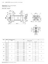
14/92 CD70 / CF70 | Hydraulic cylinders, tie rod design Dimensions: Type of mounting B (dimensions in mm) Piston 0 80 ... 200 mm Bosch Rexroth AG, RE 17016, edition: 2014-03
Open the catalog to page 14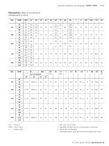
Hydraulic cylinders, tie rod design | CD70 / CG70 15/92 0AL = Piston 0 0MM = Piston rod 0 X* = Stroke length 5) Adjustable throttle valve for the end position cushioning 6) Check valve and bleeding 7) Lubricating nipple, cone head form A according to DIN 71412 RE 17016, edition: 2014-03, Bosch Rexroth AG
Open the catalog to page 15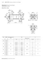
16/92 CD70 / CF70 | Hydraulic cylinders, tie rod design Dimensions: Type of mounting G (dimensions in mm) Piston 0 25 ... 63 mm Bosch Rexroth AG, RE 17016, edition: 2014-03
Open the catalog to page 16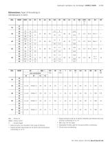
Hydraulic cylinders, tie rod design | CD70 / CG70 17/92 0AL = Piston 0 0MM = Piston rod 0 X* = Stroke length 1) Bolts and pins are included in the scope of delivery 2) Raised cylinder head except for 0 32/18 with end position cushioning "U" or "K" 3) Raised cylinder head for: 0 40/25; 0 50/36 and 0 63/45 with end position cushioning "D" or "S" 5) Adjustable throttle valve for the end position cushioning 6) Check valve and bleeding RE 17016, edition: 2014-03, Bosch Rexroth AG
Open the catalog to page 17All Bosch Rexroth - Industrial Hydraulics catalogs and technical brochures
 Check valve Type Z1S
12 Pages
 Hydraulic cylinders Mill type
80 Pages


- Connector
- Control valve
- Ball valve
- Electrical power supply connector
- Flap valve
- Round connector
- ISO valve
- Level limit switch
- Bosch Rexroth directional control valve
- Hydraulic pump
- Socket electrical connector
- Liquid level detector
- Industrial connector
- Valve for industrial applications
- Pressure switch
- Hydraulic valve