
- Catalogs
- Bosch Rexroth - Industrial Hydraulics
- Hydraulic cylinders Tie rod design - Series CDT3…Z; CGT3…Z; CST3…Z


Hydraulic cylinders Tie rod design - Series CDT3…Z; CGT3…Z; CST3…Z

Hydraulic cylinders Tie rod design - Series CDT3…Z; CGT3…Z; CST3…Z
Catalog excerpts
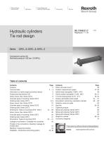
Electric Drives and Controls Linear Motion and Hydraulics I Assembly Technologies Rexroth Bosch Group Hydraulic cylinders Tie rod designSeries CDT3...Z; CGT3...Z; CST3...ZComponent series 3X Nominal pressure 160 bar (16 MPa) RE 17049/07.17 1/70 Table of contents Contents Page Information on stroke length and stroke velocity 5 Project planning software ICS 5 Areas, forces, flow: Series CDT3 6 Overview types of mounting: Series CDT3 7 Ordering code: Series CDT3 8, 9 Areas, forces, flow: Series CGT3 10 Overview types of mounting: Series CGT3 10 Ordering code: Series CGT3 11 Dimensions: Types of mounting CDT3 / CGT3 12 ... 29 Areas, forces, flow: Series CST3 30 Overview types of mounting: Series CST3 30 Ordering code: Series CST3 31 Dimensions: Types of mounting CST3 32 . 41 Leakage oil connection / Enlarged line connection 42 Position of line connections / bleeding / leakage oil / throttle valve 43 Bleeding / measuring coupling 44 Subplates - Dimensions and porting pattern 45, 46 Contents Page Position measurement system 47, 48 Swivel head (clampable): CGKA - AP 6 49 Clevis bracket (clampable): CLCB - AB 5 50, 51 Trunnion bearing block CLTA - AT 4 52, 53 Kinking, admissible stroke length 54 . 57 End position cushioning, calculation example 58 ... 62 Selection criteria for seals 63 Spare parts drawing: Series CDT3 66 Spare parts drawing: Series CGT3 67 Spare parts drawing: Series CST3 68 Project planning software Interactive Catalog System Online www.boschrexroth.com/ics
Open the catalog to page 1
2/70 Bosch Rexroth AG | Hydraulics • Installation dimensions according to ISO 6020-2 and NF/ISO 6020-2 • 13 types of mounting • Piston 0 (0AL): 25 to 200 mm • Piston rod 0 (0MM): 12 to 140 mm • Stroke lengths up to 3000 mm • Integrated guide socket for fast and easy maintenance • Self-adjusting or adjustable end position cushioning as option • Patented safety vent for easy and safe bleeding • Easy assembly thanks to freely selectable position of the line connections at head and base Maximum operating pressure (only static load): 210 bar (21 MPa) Static test pressure: 240 bar (24 MPa) For admissible...
Open the catalog to page 2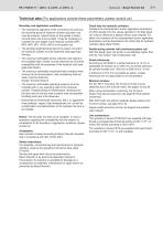
Hydraulics | Bosch Rexroth AG Technical data (For applications outside these parameters, please consult us!) Boundary and application conditions: • The mechanical alignment of the movement axis and thus the mounting points of hydraulic cylinder and piston rod must be ensured. Lateral forces on the guides of piston rod and piston are to be avoided. It may be necessary to consider the own weight of the hydraulic cylinder (MP1, MP3, MP5, MT1, MT2 or MT4) or the piston rod. • The bending length/bending load of the piston rod and/or the hydraulic cylinder must be observed (see page topic Kinking)....
Open the catalog to page 3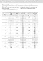
4/70 Bosch Rexroth AG | Hydraulics Stroke velocity: See information on stroke length and stroke velocity, higher retraction velocity of the piston rod, drag-out losses of the stroke velocity on request. medium may result. If necessary, please consult us. If the extension velocity is considerably higher than the
Open the catalog to page 4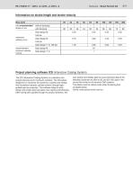
Hydraulics | Bosch Rexroth AG Information on stroke length and stroke velocity 0AL (mm) The ICS (Interactive Catalog System) is a selection and project planning aid for hydraulic cylinders. The ICS allows designers for machines and systems to quickly and reliably find the perfect hydraulic cylinder solution through logic-guided type key enquiries. This software helps to solve design and project planning tasks more quickly and efficiently. After having been guided through the product selection, the user quickly and reliably gets the exact technical data of the selected component as well as 2D...
Open the catalog to page 5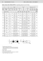
6/70 Bosch Rexroth AG | Hydraulics Theoretical static cylinder force (without consideration of the efficiency and admissible load for attachment parts like e.g. swivel heads, plates or valves, etc.) 4) With operating pressures up to 210 bar only on request 5) Larger stroke lengths upon request
Open the catalog to page 6
Overview types of mounting: Series CDT3 (for operating pressure up to 210 bar) CDT3 ME5 (ISO/DIN/NF)
Open the catalog to page 7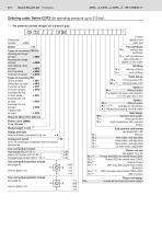
8/70 Bosch Rexroth AG | Hydraulics The preferred cylinder designs are marked in gray. Further details in the plain text Types of mounting DIN/ISO Rectangular flange at head = ME5 Rectangular flange at base = ME6 Self-aligning clevis at base = MP5 Types of mounting ISO Clevis at base = MP1 Extended tie rod, on both sides = MX1 Tapped hole at head 2)= MX5 Test certificate W = without test certificate C = with acceptance test certificate 3.1 based on EN 10204 Oil filling without oil filling with oil filling Color set-up W = Priming class CP3 Option 2 W = Without option Y = Specify the piston rod...
Open the catalog to page 8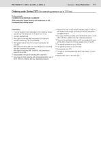
Ordering code: Series CDT3 (for operating pressure up to 210 bar) Order example: CDT3MP5/50/36/300Z3X/B11HHDMWW When selecting, please observe the limitations on the corresponding catalog pages! the max. stroke length available, page 6, and the admissible stroke length (according to kinking calculation) on pages 54 to 57 Trunnion position freely selectable; when ordering, always specify the "XV" dimension in the plain text in mm. With type of mounting MS2 and piston Ø 25 and end position cushioning, "E" is not possible With piston Ø 25 to 100 mm: only line connection "B" possible. With piston...
Open the catalog to page 9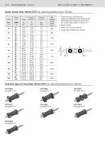
10/70 Bosch Rexroth AG | Hydraulics 1 Theoretical static cylinder force (without consideration of the efficiency and admissible load for attachment parts like e.g. swivel heads, plates or valves, etc.) 4) Larger stroke lengths upon request
Open the catalog to page 10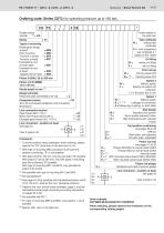
Hydraulics | Bosch Rexroth AG 11/70 Further details in the plain text Types of mounting Rectangular flange at head = ME5 Extended tie rod, on both sides = MX1 Tapped hole at head = MX5 Piston 0 (0AL) 25 to 200 mm Piston rod 0 (0MM) 12 to 140 mm Stroke length in mm 14) Design principle Head and base connected to tie rod = Z 30 to 39 unchanged installation and connection dimensions Line connection/version Pipe thread (ISO 1179-1) = B Enlarged pipe thread (ISO 1179-1) 17)= S Line connection / position at head see page 43 View to piston rod Test certificate W = without test certificate C = with acceptance...
Open the catalog to page 11All Bosch Rexroth - Industrial Hydraulics catalogs and technical brochures
 Check valve Type Z1S
12 Pages
 Hydraulic cylinders Mill type
80 Pages


- Connector
- Control valve
- Ball valve
- Electrical power supply connector
- Flap valve
- Check valve
- ISO valve
- Circular connector
- Bosch Rexroth directional control valve
- Level limit switch
- Hydraulic pump
- Socket electrical connector
- Liquid level detector
- Industrial connector
- Valve for industrial applications
- Pressure switch
- Hydraulic valve