- Catalogs
- Bosch Rexroth - Industrial Hydraulics
- Hydraulic cylinders Mill type
Hydraulic cylinders Mill type
1 /80Pages

Hydraulic cylinders Mill type
1 /80Pages
Catalog excerpts

Electric Drives Linear Motion and and Controls I Hydraulics I Assembly Technologies Rexroth Bosch Group Hydraulic cylinders Mill typeSeries CDH2 / CGH2 / CSH2Component series 3X Nominal pressure 250 bar (25 MPa) RE 17335/07.17 1/78 Table of contents Contents Features 1 Project planning software ICS 3 Diameters, areas, forces, flow 4 Overview types of mounting: Series CDH2 and CGH2 5 Ordering code series CDH2 and CGH2 6 ... 9 Types of mounting and dimensions CDH2 and CGH2 10 ... 21 Ordering code, overview of types of mounting CSH2 22, 23 Types of mounting and dimensions CSH2 24 ... 35 Subplates for valve mounting 38 ... 41 Bleeding / measuring coupling 42 Position measurement system 46 ... 48 Features - Standards: DIN 24333, ISO 6022 - 6 types of mounting - Piston 0 (0AL): 40 to 320 mm - Piston rod 0 (0MM): 25 to 220 mm - Stroke lengths up to 6 m - Self-adjusting and adjustable end position cushioning Fork clevis CCKB 50, 51 Swivel head CGKD 52, 53 Trunnion bearing block CLTB 54, 55 Clevis bracket CLCA 56, 57 Clevis bracket CLCD 58, 59 Admissible stroke length 60 ... 62 Selection criteria for seals 66 Spare parts: Series CDH2 73 Spare parts: Series CGH2 74 Spare parts: Series CSH2 MP3 and MP5 75 Project planning software Interactive Catalog System Online www.boschrexroth.com/ics
Open the catalog to page 1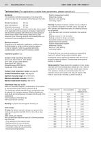
2/78 Bosch Rexroth AG | Hydraulics Standards: The installation dimensions and types of mounting of the cylinder comply with the standards DIN 24333 and ISO 6022. Nominal pressure: 250 bar Static test pressure: 375 bar Reduced test pressure: 315 bar The maximum operating pressures must be less than or equal to the applicable nominal pressures and apply to applications with shock-free operation with reference to excess pressure and/or external loads. With extreme loads like e.g. high sequence cycle, mounting elements and threaded piston rod connections must be designed for durability. Minimum pressure:...
Open the catalog to page 2
Hydraulics | Bosch Rexroth AG Technical data (For applications outside these parameters, please consult us!) Boundary and application conditions: • The mechanical alignment of the movement axis and thus the mounting points of hydraulic cylinder and piston rod must be ensured. Lateral forces on the guides of piston rod and piston are to be avoided. It may be necessary to consider the own weight of the hydraulic cylinder (MP3/MP5 or MT4) or the piston rod. • The bending length/bending load of the piston rod and/or the hydraulic cylinder must be observed (see page topic Kinking). • The maximum admissible...
Open the catalog to page 3
4/78 Bosch Rexroth AG | Hydraulics 1 Theoretical, static cylinder force 2) Stroke velocity (without consideration of the efficiency and admissible load for attachment parts such as swivel heads, plates, or valves, etc.) Not standardized 2 Including stroke length 3) Stroke tolerances must not be added to the tolerances listed in this table.
Open the catalog to page 4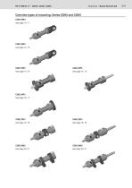
Overview types of mounting: Series CDH2 and CGH2 CDH2 MP3 see page 10, 11
Open the catalog to page 5
6/78 Bosch Rexroth AG | Hydraulics Head and base flanged = A Component series 30 to 39 unchanged installation and connection dimensions = 3X Line connection / version according to ISO 1179-1 (pipe thread ISO 228-1) = B according to ISO 9974-1 (metric thread ISO 261) 33)= M Flange porting pattern according to ISO 6162-1 4) 21)= F tab. 2 type 1 (= SAE 3000 PSI) Flange porting pattern according to ISO 6162-2 4) 9)= D tab. 2 type 1 (= SAE 6000 PSI) Flange porting pattern according to ISO 6164 tab. 1 1) 4)= K Flange porting pattern according to ISO 6164 tab. 2 4)= H according to ISO 1179-1 (pipe thread...
Open the catalog to page 6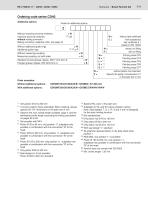
Hydraulics | Bosch Rexroth AG Ordering code series CDH2Additional options Fields for additional options Without inductive proximity switches = W without test certificate with acceptance test certificate 3.1 based on EN 10204 without oil filling with oil filling Priming class CP3 Painting class CP4 Painting class CP5 Painting class CP6 Painting class CP7 Inductive proximity switches 37)= E without mating connector Mating connector, separate order, see page 44 Without additional guide rings = W Without measuring coupling = W Measuring coupling, on both sides = A Standard conical grease nipples,...
Open the catalog to page 7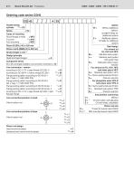
8/78 Bosch Rexroth AG | Hydraulics Ordering code series CGH2 CG Double-acting cylinder 18) = CG Series = H2 Types of mounting Round flange at head = MF3 Trunnion 2) = MT4 Piston 0 (0AL) 40 to 320 mm Piston rod 0 (0MM) 25 to 220 mm Stroke length in mm 3) Design principle Head and base flanged = A Component series 30 to 39 unchanged installation and connection dimensions = 3X Line connection / version according to ISO 1179-1 (pipe thread ISO 228-1) = B according to ISO 9974-1 (metric thread ISO 261) 33)= M Flange porting pattern according to ISO 6162-1 21)= F tab. 2 type 1 (^ SAE 3000 PSI) Flange...
Open the catalog to page 8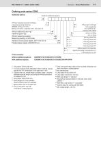
Hydraulics | Bosch Rexroth AG Ordering code series CGH2Additional options Fields for additional options Without inductive proximity switches = W without test certificate with acceptance test certificate 3.1 based on EN 10204 without oil filling with oil filling Priming class CP3 Painting class CP4 Painting class CP5 Painting class CP6 Painting class CP7 Inductive proximity switches 37) = E without mating connector Mating connector, separate order, see page 44 Without additional guide rings = W Additional guide rings 10), 28) = F Without measuring coupling = W Measuring coupling, on both sides...
Open the catalog to page 9
CDH2 MP3: with seal design "A", "B" and ØAL 160 to 320 mm
Open the catalog to page 10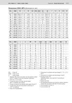
Hydraulics | Bosch Rexroth AG 11/78 0AL = Piston 0 0MM = Piston rod 0 X* = Stroke length 1) Bleeding: With view to the piston rod, the position is offset by 90° in relation to the line connection (clockwise) 3) Thread size does not comply with ISO 6022; M50 x 2 available upon request 4) Flange connections see separate table pages 36 and 37 5) Throttle valve only with end position cushioning "E" (180° for bleeding) 7) Dimensions for cylinders with seal design M, T, G, L, R, S and V 8) Dimensions for cylinders with seal design A and B 10) Standard version "W" Lubricating nipple, cone head form...
Open the catalog to page 11All Bosch Rexroth - Industrial Hydraulics catalogs and technical brochures
 Check valve Type Z1S
12 Pages


- Control valve
- Ball valve
- Electrical power supply connector
- Flap valve
- Check valve
- ISO valve
- Level limit switch
- Bosch Rexroth directional control valve
- Hydraulic pump
- Socket electrical connector
- Liquid level detector
- Industrial connector
- Valve for industrial applications
- Pressure switch
- Hydraulic valve
- 2-channel valve