
- Catalogs
- Bosch Rexroth - Industrial Hydraulics
- Directional spool valves, pilot-operated,with hydraulic or electro-hydraulic actuation type WEH and WH


Directional spool valves, pilot-operated,with hydraulic or electro-hydraulic actuation type WEH and WH

Directional spool valves, pilot-operated,with hydraulic or electro-hydraulic actuation type WEH and WH
The document outlines the features of directional spool valves available in 4/3-, 4/2-, or 3/2-way versions. These valves can be actuated electro-hydraulically (type WEH) or hydraulically (type WH) and are designed for subplate mounting with an ISO 4401 porting pattern. They include options for spring or pressure centering, wet-pin DC or AC solenoids, manual override, switching time adjustment, preload valve, and stroke setting.
This section provides detailed specifications for selecting the appropriate valve configuration, including pressure ratings, actuation types, size, control spool return, pilot oil flow, switching time adjustment, electrical connection, spool position monitoring, stroke setting, throttle insert, preload valve, pressure reducing valve, and seal material.
Symbols for valves with 2 and 3 spool positions are provided, illustrating various configurations and actuation types to help understand the flow paths and control mechanisms.
The document explains the function of WEH and WH valve types. WEH is an electro-hydraulic directional spool valve controlling flow start, stop, and direction, consisting of a main valve, control spool, return springs, and a pilot control valve with solenoids. WH is hydraulically actuated with a similar structure but different actuation method.
Details on pilot oil supply include internal and external supply options, emphasizing the importance of proper pilot oil supply for valve operation.
Technical specifications include a maximum operating pressure of 350 bar and a maximum flow of 1100 l/min. The document advises consulting for applications outside specified values.
Performance data for various valve sizes (NG10, NG16, NG25, NG32) are presented, measured under specific conditions, helping assess valve performance under different operational scenarios.
Detailed dimensions for different valve sizes are provided, along with mounting options and stroke settings, crucial for installation and integration into hydraulic systems.
Options for switching time adjustment and preload valve configurations are discussed, offering flexibility in valve operation and performance tuning.
The document concludes with project planning information and further references, aiding in the comprehensive understanding and application of the valves in hydraulic systems.
This document provides technical specifications and performance data for Bosch Rexroth AG's directional spool valves, specifically the WEH and WH series, including detailed information on operating pressures, flow rates, and valve dimensions.
- Operating Pressure: Valves operate at maximum pressures ranging from 70 to 350 bar, depending on configuration and symbol used.
- Flow Rates: Maximum flow rates (qV max) are specified for both 2-spool and 3-spool position valves, with values varying based on operating pressure and valve symbol.
- Spring and Hydraulic End Positions: Details on spring and hydraulic end positions for various valve symbols, indicating maximum flow rates and pressures at which these positions are maintained.
- Performance limits are determined under specific conditions, including solenoid operating temperature and voltage variations.
- Important notices highlight that performance limits apply to dual flow directions and may be lower with single flow directions.
- ∆p-qV characteristic curves are provided for different valve symbols, showing the relationship between flow rate and pressure differential.
- Detailed dimensions are provided for NG10, NG16, NG25, and NG32 valve sizes, including mounting instructions and required surface quality.
- Instructions for stroke setting and mounting options are included, with specific adjustment ranges for different valve sizes.
- Valve mounting screws and their specifications are listed, with torque requirements and material numbers.
- Manual override options and solenoid configurations are discussed, with warnings about simultaneous solenoid actuation.
- Subplates and valve mounting screws are available for separate order, with references to additional data sheets for more information.
Detailed specifications for stroke settings and mounting options for directional spool valves, specifically versions "W.H 22" and "W.H 25", including dimensions in millimeters for various spool positions and valve sides (A and B).
The switching time of the main valve is influenced by a twin throttle check valve. The document outlines the procedure for modifying supply to discharge control, emphasizing that modifications should only be performed by authorized specialists or at the factory.
Discusses the pressure differential characteristics of preload valves, necessary for valves with depressurized circulation and internal pilot oil supply, providing part numbers for preload valves based on valve size and component series.
Adherence to the Machinery Directive 2006/42/EC is required. Additional data sheets are referenced for further information on MTTFD values, shock and vibration loads, and other technical specifications.
Lists various data sheets for additional information on related components and systems, including hydraulic fluids, reliability characteristics, and assembly instructions, along with contact information for Bosch Rexroth AG.
Catalog excerpts

Directional spool valves, pilot-operated, with hydraulic or electro-hydraulic actuation type WEH and WH ▶▶ ▶▶ ▶▶ ▶▶ Size 10 … 32 Component series 4X; 6X; 7X Maximum operating pressure 350 bar Maximum flow 1100 l/min ▶▶ 4/3-, 4/2- or 3/2-way version ▶▶ Types of actuation (internal or external pilot control): –– Electro-hydraulic (type WEH) –– Hydraulic (type WH) ▶▶ For subplate mounting ▶▶ Porting pattern according to ISO 4401 ▶▶ Spring or pressure centering, spring end position or hydraulic end position ▶▶ Wet-pin DC or AC solenoids, optional ▶▶ Electrical connection as individual or central connection ▶▶ Optional versions: –– Manual override –– Switching time adjustment –– Preload valve in channel P of the main valve –– Stroke setting and/or spool position monitoring Features1 Ordering code 2…4 Symbols 5…9 Function, section 10 … 12 Pilot oil supply 13 … 14 Technical data 15 … 18 Characteristic curves, performance limits 19 … 28 Dimensions 29 … 35 Stroke setting, mounting options 36, 37 Switching time adjustment 38 Pressure reducing valve "D3" 38 Preload valve 39 Proj
Open the catalog to page 1
2/40 WEH; WH | Directional spool valve Bosch Rexroth AG, RE 24751, edition: 2020-03
Open the catalog to page 2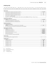
Directional spool valve | WEH; WH 3/40 Pst = pilot pressure pst min = minimum pilot pressure PTank = tank pressure Po = cracking pressure RE 24751, edition: 2020-03, Bosch Rexroth AG
Open the catalog to page 3
1) ► 2 switching positions (hydraulic end position): only symbols C, D, K, Z, Y ► 3 switching positions (hydraulically centered): only NG16, NG25 ("4W.H 25") and NG32 2) With electro-hydraulic actuation only (type WEH) 3) Pilot oil supply X or return Y external: ► The maximum admissible operating parameters of the pilot control valve must be observed (see data sheet 23178). ► Minimum pilot pressure: please observe page 16. ► Maximum pilot pressure: please observe page 16. 4> Pilot oil supply internal (version "ET" and "E"): ► Minimum pilot pressure: please observe page 16. ► Maximum pilot pressure:...
Open the catalog to page 4
Directional spool valve | WEH; WH 5/40 Symbols: 2 spool positions 1 Only for NG10 and 25 ("4W.H 22") with 3/2-way version; if operating pressure > tank pressure, port T is to be used as a leakage port! Ordering code Symbol Control spool return a, X a, X Type of actuation Type WH (hydraulic) Type WEH (electro-hydraulic) a, X aAT b, Y APPT AP PT 33 b 33b RE 24751, edition: 2020-03, Bosch Rexroth AG
Open the catalog to page 5
WEH; WH | Directional spool valve Symbols: 3 spool positions E1) Example: Symbol E with actuating side "a" → ordering code ..EA.. Ordering code Symbol Actuating side Control spool return Bosch Rexroth AG, RE 24751, edition: 2020-03
Open the catalog to page 6
Directional spool valve | WEH; WH 7/40 Symbols for valves with 2 spool positions Valve with spring end position Valve with hydraulic end position Type WEH…/…ET… Type WEH…/…E…
Open the catalog to page 7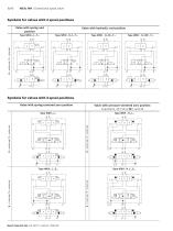
WEH; WH | Directional spool valve Symbols for valves with 2 spool positions Valve with spring end position Valve with hydraulic end position Type WEH…/…T… Symbols for valves with 3 spool positions Valve with spring-centered zero position Valve with pressure-centered zero position only NG16, 25 ("W.H 25") and 32 Bosch Rexroth AG, RE 24751, edition: 2020-03 Type WEH…/…E…
Open the catalog to page 8
Directional spool valve | WEH; WH 9/40 Valve with spring-centered zero position Valve with pressure-centered zero position only NG16, 25 ("W.H 25") and 32 Type WEH . H../...ET... rC c Cl) II >-To c CD C II X Notice: 3-spool position valves, pressure-centered, preferably with external pilot oil supply and/or return ("no code", "E") For preconditions for internal pilot oil supply and/or return ("ET", "T"), see page 4 and 15. RE 24751, edition: 2020-03, Bosch Rexroth AG
Open the catalog to page 9
WEH; WH | Directional spool valve Function, section: Type WEH 4 Directional valves type WEH… The valve type WEH is a directional spool valve with electro-hydraulic actuation. It controls the start, stop and direction of a flow. The directional valves basically consist of the main valve with housing (1), the main control spool (2), one or two return springs (3.1) and (3.2), as well as the pilot control valve (4) with one or two solenoids "a" (5.1) and/or "b" (5.2). For unobjectionable functioning, the hydraulic system has to be bled properly. For valves with three spool positions, the main control...
Open the catalog to page 10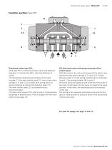
Directional spool valve | WEH; WH 11/40 Function, section: Type WH 11 1 2 Directional valves type WH… Valve type WH is a directional spool valve with hydraulic actuation. It controls the start, stop and direction of a flow. The directional valve basically consists of the valve housing (1), the main control spool (2), one or two return springs (3.1) and (3.2) at valves with spring return or spring centering as well as the diversion plate (11). The main control spool (2) is actuated directly by pressurization. The main control spool (2) is held in zero or initial position by springs or pressurization....
Open the catalog to page 11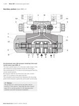
WEH; WH | Directional spool valve Function, section: Type WEH…H 4/3 directional valve with pressure centering of the main control spool, type WEH…H The main control spool (2) in the main valve is kept in the zero position by pressurization of the two front faces. One centering bush (12) rests on the housing and fixes the control spool position. By pressure relief of one front face, the main control spool (2) is moved to the spool position. The unloaded control spool face displaces the returning pilot oil into channel Y (external) via the pilot control valve. Notices: The springs (3.1) and (3.2)...
Open the catalog to page 12
Directional spool valve | WEH; WH 13/40 Pilot oil supply (schematic illustration) NG10 2 1 Plug screw M6 according to DIN 906, wrench size 3 – pilot oil return 2 Plug screw M6 according to DIN 906, wrench size 3 – pilot oil supply 3 Plug screw M12 x 1.5 according DIN 906, wrench size 6 – pilot oil supply Pilot oil supply external: 2, 3 closed internal: 2, 3 open Pilot oil return external: 1 closed internal: 1 open Further explanations on page 14. RE 24751, edition: 2020-0
Open the catalog to page 13All Bosch Rexroth - Industrial Hydraulics catalogs and technical brochures
 Check valve Type Z1S
12 Pages
 Hydraulic cylinders Mill type
80 Pages


- Connector
- Ball valve
- Cylinder
- Electrical power supply connector
- Flap valve
- ISO valve
- Circular connector
- Bosch Rexroth directional control valve
- Level limit switch
- Hydraulic pump
- Socket electrical connector
- Liquid level detector
- Hydraulic cylinder
- Industrial connector
- Valve for industrial applications
- Pressure switch
- Hydraulic valve