- Catalogs
- Bosch Rexroth - Electric Drives and Controls
- IndraMotion MTX 14VRS


- Products
- Catalogs
- News & Trends
- Exhibitions
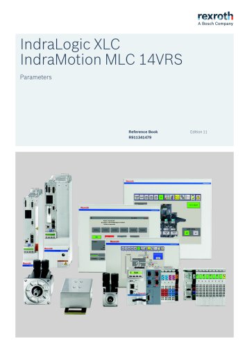
IndraMotion MTX 14VRS

IndraMotion MTX 14VRS
- Definitions: Clarifies terms such as component, control system, device, electrical equipment, electric drive system, installation, machine, manufacturer, product, project planning manual, qualified persons, and user.
- General Information: Stresses the necessity of reading and understanding all safety instructions and user documentation before working with electric drive and control system components.
- Requirements for Safe Use: Lists prerequisites for safe operation, including proper transport, storage, mounting, installation, and maintenance.
- Hazards by Improper Use: Highlights potential dangers such as electric shock, unintended motor movements, and risks to individuals with pacemakers or metal implants.
- Protection Against Electrical Hazards: Provides detailed instructions for grounding and connecting components to prevent electric shock.
- Protection Against Dangerous Movements: Discusses risks of faulty motor control due to wiring errors, operator mistakes, or defective components.
- Machine Safety: Ensure safety devices are active to prevent unintended movements.
- Electromagnetic Fields: Caution for individuals with medical implants or pregnant women near electromagnetic fields.
- Hot Surfaces: Avoid contact with hot components.
- Handling and Mounting: Use proper tools and protective equipment to prevent injuries during installation.
- Battery Safety: Handle batteries carefully to avoid explosions or leaks.
- Pressurized Systems: Handle pressurized lines with care to prevent injuries.
- Description: Central to the IndraMotion MTX systems, offering digital I/Os and various interfaces.
- Performance Data: Systems vary in the number of axes, spindles, and NC channels they support.
- Technical Data: Details on processors, RAM, interfaces, and I/O capabilities for each control model.
- Power Supply: Operates on 24 V DC with specific voltage tolerances.
- Ambient Conditions: Specifies operational and storage temperature ranges, humidity, and atmospheric pressure limits.
- Acceleration: 1 g at 57-150 Hz according to EN 60068-2-6.
- Maximum shock: 15 g according to EN 60068-2-27, with no malfunctions.
- Ambient conditions require dust-free air and protection class IP 54 according to DIN VDE 0470-1.
- Operating temperature should remain below 45°C, with a maximum of 55°C if air circulates.
- Sercos X7E1, X7E2: Ethernet 100BaseT, max cable length 100 m, CAT5e with S/STP, 10 or 100 Mbit/s.
- Profinet X7E3, X7E4: Similar specifications as Sercos.
- PROFIBUS DP X7P: RS 485, shielded 2-wire, max transfer rate 12 MBauds.
- Ethernet X7E5: Same specifications as Sercos and Profinet.
- Ready contact X2R: Opens under specific conditions like voltage drops or watchdog expiration.
- Eight digital inputs and outputs with specific address assignments.
- Inputs have reverse voltage protection and specific voltage/current requirements.
- Outputs are semiconductor type with overload protection and specific current/voltage ratings.
- Single-line LCD display with four operating keys for menu navigation and input functions.
- Reset button for module restart without switching off supply voltages.
- Status menu provides information on Ethernet address, firmware version, CPU temperature, and more.
- Automation Outlet (AO): Fixed connection hardware where the AI network ends.
- Automation Island (AI): Combination of systems that control, monitor, and protect the process of a system.
- Network Interface (NI): Interface between the wiring for fixing the device and the device network.
- Field Bus Interface (FI): Connects field bus devices.
- Power Drive System (PDS): Component of the network infrastructure.
- General Requirements: Installation must follow planning documentation.
- Cable Installation: Cables must be protected from mechanical damage.
- Strain Relief: Devices should be used to prevent damage from tensile forces.
Introduction: Comprehensive system description for the IndraMotion MTX 14VRS by Bosch Rexroth AG, focusing on electric drives and controls.
Specifications: Outlines specifications related to the MTX system, including network properties, wiring components, and protective measures for communication cables.
Installation Procedures: Detailed instructions for device installation, including the installation of cables in cabinets, grounding equipment, and the installation of Sercos networks.
Safety and Standards: Safety instructions are emphasized, including hazard warnings and safety alert symbols.
Recommendations and Best Practices: Recommendations for selecting and using wiring components, as well as protecting communication cables from mechanical damage.
Support and Feedback: Customer feedback and suggestions are addressed, with contact information for the helpdesk and service hotline provided for further support.
Additional Information: Includes an index for easy navigation and references to various modules and components related to the MTX system.
Catalog excerpts

IndraMotion MTX 14VRS System Description Project Planning Manual R911342640
Open the catalog to page 1
DOK-MTX***-SYS*DES*V14-PR03-EN-P IndraMotion MTX 14VRS System Description IndraMotion MTX 14VRS System Description Type of Documentation Document Typecode Internal File Reference Project Planning Manual DOK-MTX***-SYS*DES*V14-PR03-EN-P RS-5e64ee410d19898c0a6846a5016285f0-3-en-US-6 Release Note date 2014-09 Extending the system limits of MTX New chapter “Hand-held terminal VH2110" New target CML75 New multitouch display VDP15.3, 18.3, 21.3 New machine control panel VAM 15.1, 21.1 © Bosch Rexroth AG 2015 This document, as well as the data, specifications and other information set forth in it, are...
Open the catalog to page 2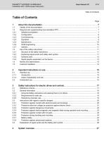
DOK-MTX***-SYS*DES*V14-PR03-EN-P IndraMotion MTX 14VRS System Description Table of Contents Page
Open the catalog to page 3
DOK-MTX***-SYS*DES*V14-PR03-EN-P IndraMotion MTX 14VRS System Description Table of Contents Page
Open the catalog to page 4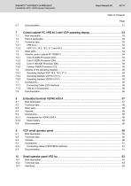
DOK-MTX***-SYS*DES*V14-PR03-EN-P IndraMotion MTX 14VRS System Description Table of Contents Page 6.7
Open the catalog to page 5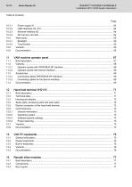
DOK-MTX***-SYS*DES*V14-PR03-EN-P IndraMotion MTX 14VRS System Description
Open the catalog to page 6
DOK-MTX***-SYS*DES*V14-PR03-EN-P IndraMotion MTX 14VRS System Description Table of Contents Page 14.4 14.4.1 14.4.2 14.5
Open the catalog to page 7
DOK-MTX***-SYS*DES*V14-PR03-EN-P IndraMotion MTX 14VRS System Description
Open the catalog to page 8
DOK-MTX***-SYS*DES*V14-PR03-EN-P IndraMotion MTX 14VRS System Description About this documentation About this documentation Validity of the documentation Target group This documentation is intended for users wanting to inform themselves about the IndraMotion MTX control system. Overview on target groups and product phases In the following illustration, the framed activities, product phases and target groups refer to the present documentation. Example: The target group "Commissioning engineer" can "configure" in the product phase "Engineering" using this documentation. Product phases Mounting...
Open the catalog to page 9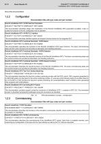
DOK-MTX***-SYS*DES*V14-PR03-EN-P IndraMotion MTX 14VRS System Description About this documentation Configuration Documentation titles with type codes and part numbers Rexroth IndraMotion MTX 14VRS Machine Parameters DOK-MTX***-MA*PAR**V14-RERS-DE-P, R911342630 This documentation describes design and modification of the Rexroth IndraMotion MTX parameters available. It also in‐ cludes the functions of the NC configurator and its operation. Rexroth IndraMotion MTX 14VRS PLC Interface DOK-MTX***-PLC*INT*V14-PRRS-DE-P, R911342622 This documentation describes interface signals and program function...
Open the catalog to page 10
DOK-MTX***-SYS*DES*V14-PR03-EN-P IndraMotion MTX 14VRS System Description About this documentation Rexroth IndraWorks 14VRS Basic Libraries IndraLogic 2G DOK-IL*2G*-BASLIB**V14-LIRS-DE-P, R911343920 This documentation describes the system-comprehensive PLC libraries. Rexroth IndraWorks 14VRS Field Buses DOK-IWORKS-FB******V14-APRS-DE-P, R911341485 This documentation describes field bus and local periphery connections supported by the systems IndraLogic XLC, IndraMotion MLC and IndraMotion MTX. This documentation focuses on the configuration, parameterization, commission‐ ing and diagnostics of...
Open the catalog to page 11
DOK-MTX***-SYS*DES*V14-PR03-EN-P IndraMotion MTX 14VRS System Description About this documentation Rexroth IndraMotion MTX 14VRS Programming Manual DOK-MTX***-NC**PRO*V14-RERS-DE-P, R911342634 This documentation describes the standard programming of the Rexroth IndraMotion MTX control. Apart from the basics of NC programming, the use of NC functions according to DIN 66025 as well as the NC functions with high-level language syntax and CPL functions are described. Rexroth IndraMotion MTX 14VRS Standard NC Operation DOK-MTX***-NC*OP***V14-APRS-DE-P, R911342632 This documentation describes the operation...
Open the catalog to page 12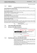
DOK-MTX***-SYS*DES*V14-PR03-EN-P IndraMotion MTX 14VRS System Description About this documentation AddOns Documentation titles with type codes and part numbers Rexroth IndraMotion MTX 11VRS Action Recorder DOK-MTX***-ACR*****V11-APxx-DE-P, R911329943 This documentation describes the MTX action recorder. It includes the installation and commissioning as well as interface signals, application and operation. Rexroth IndraMotion MTX efficiency workbench 14VRS MTX cta, MTX ega DOK-MTX***-EWB*****V14-APRS-DE-P, R911343916 This documentation describes the mode of operation and the area of application...
Open the catalog to page 13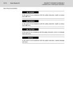
DOK-MTX***-SYS*DES*V14-PR03-EN-P IndraMotion MTX 14VRS System Description About this documentation DANGER In the event of non-compliance with this safety instruction, death or serious injury will occur. WARNING In the event of non-compliance with this safety instruction, death or serious injury will occur. CAUTION In the event of non-compliance with this safety instruction, minor or moderate injury can occur. NOTICE In the event of non-compliance with this safety instruction, material damage can occur.
Open the catalog to page 14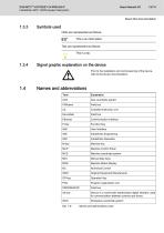
DOK-MTX***-SYS*DES*V14-PR03-EN-P IndraMotion MTX 14VRS System Description About this documentation Symbols used Hints are represented as follows: This is an information. Tips are represented as follows: This is a tip. Signal graphic explanation on the device Prior to the installation and commissioning of the device, refer to the device documentation. krax Names and abbreviations Term Axis coordinate system Compiled Instruction List Communication interface User Interface IndraWorks Engineering IndraWorks Operation Machine Control Panel Machine coordinate system Manual data input Machine Status...
Open the catalog to page 15
DOK-MTX***-SYS*DES*V14-PR03-EN-P IndraMotion MTX 14VRS System Description About this documentation Customer feedback Customer requests, comments or suggestions for improvement are of great importance to us. Please email your feedback on the documentations to [email protected]. Directly insert comments in the electronic PDF document and send the PDF file to Bosch Rexroth.
Open the catalog to page 16
DOK-MTX***-SYS*DES*V14-PR03-EN-P IndraMotion MTX 14VRS System Description Introduction Bosch Rexroth products are developed and manufactured according to the state-of-the-art. The products are tested prior to delivery to ensure operating safety and reliability. The products may only be used as intended. If they are not used as intended, situations occur that result in damage to property or personal injury due to in‐ correct use of products. Bosch Rexroth shall not assume any warranty, liability or payment of damages in case of damage resulting from a non-intended use of the products; the use...
Open the catalog to page 17All Bosch Rexroth - Electric Drives and Controls catalogs and technical brochures
 Single-axis BASIC OPEN LOOP
4 Pages
 Sercos III
24 Pages
 MTX micro
28 Pages
 IndraMotion MLC
28 Pages
 Asynchronous Motors MAD / MAF
312 Pages
 MSK Synchronous Motors
221 Pages
 IoT Gateway
14 Pages



Archived catalogs
 Drive Controllers HCQ, HCT
148 Pages