 Website:
Bosch Rexroth Components for Mobile Robotics
Group: BOSCH REXROTH
Catalog excerpts
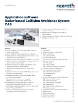
Application software Radar-based Collision Avoidance System CAS ▶ Collision warning and avoidance system for mobile machinery ▶ Based on Radar Off-Highway and MM7.10 inertial sensor ▶ Software solution on Rexroth control unit RC5-6/40 ▶ Release 100, Version 1.0.0 ▶ Easy to integrate into existing hydrostatic or electric Typical applications and benefits System description Functional description 4.3 Electronic interfaces and functionality Electrical interfaces drivetrain topologies ▶ Easy to integrate with existing HMIs (e.g., displays) ▶ Radar sensor can simultaneously detect and track up to 40 stationary or moving objects ▶ System can cover both front and rear side of the vehicle ▶ System monitors the nearfield and can avoid collisions when moving at higher speeds ▶ Assistance function can trigger warnings and active stopping (optional) to avoid collisions ▶ System predicts the ego motion to reduce false positives Parameter setting and diagnostics Functional safety considerations Project engineering and ordering information 8.4 Project specific parameters 8.6 Documents and tools container Valid standards and related documentation ▶ System can be temporarily muted for maneuvering close to objects in confined areas ▶ Blindness detection to inform the operator about limited system availability ▶ Easy application with commissioning tool BODAS‑service for parameter optimization ▶ Developed for collision warning and avoidance according to the definition by ISO 21815-3 ▶ Developed according to safety standard EN ISO 13849, ISO 25119 and ISO 19014 ▶ Starter kit available for prototypical evaluation, including DI5 with visualization GUI
Open the catalog to page 1
CAS | Application software Introduction 1 Introduction Collisions of mobile machinery with stationary or moving objects pose a serious hazard during machine operation. In For the considered application, the system needs to be particular, impaired visibility can lead to dangerous situa- provided with parameters describing the mounting orienta- tions for operators, machines and bystanders. Assistance tion of the sensors and vehicle specific parameters. The functions based on surround sensing technology can con- small number of parameters allows for small commissioning tribute to safer machine...
Open the catalog to page 2
Application software | CAS Typical applications and benefits 2 Typical applications and benefits The system for radar-based collision avoidance (CAS) aims at all driving applications. Typical examples include wheeled loaders, telescopic handlers, dumpers, tractors, municipal vehicles, mobile excavators etc. The system is prepared to monitor either one side only (e.g., the rear side of a wheeled loader) or to use a second radar for monitoring the opposite side (e.g., the front and rear side of a municipal vehicle). The system explicitly considers the driving direction, i.e., only the...
Open the catalog to page 3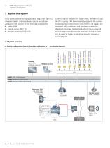
CAS | Application software System description 3 System description For a one-sided monitoring application (e.g., rear side of a Communication between the Radar OHW, the MM7.10 and wheeled loader), the radar-based system for collision the RC is purely CAN based partially supports the commu- avoidance CAS consists of the following components: nication protocol described in ISO 21815‑2. All signals are enhanced with checksums and message counters for diagnostic coverage. Analog (redundant) inputs are used to indicate an override request (muting). Analog outputs can be used to trigger an alarm...
Open the catalog to page 4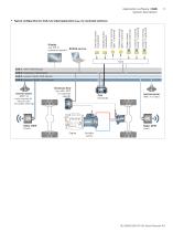
Application software | CAS System description Collision warning buzzer 2 (optional) Collision warning buzzer 1 (optional) System status buzzer (optional) Collision warning light 2 (optional) Collision warning light 1 (optional) Standby button (redundant) Display e.g. DI5 or BODAS-service customer specific Override button (redundant) ▼ Typical configuration for CAS, two-sided application (e.g., for municipal vehicles) I/Os CAN 1: HMI (1000 kbaud) CAN 2: Drivetrain (250 kbaud) CAN 3: Sensors REAR (500 kbaud) CAN 4: Sensors FRONT (500 kbaud) (only required for vehicles with articulated...
Open the catalog to page 5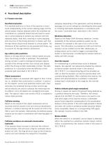
CAS | Application software Functional description 4 Functional description 4.1 Feature overview Nearfield evaluation The nearfield behind or in front of the machine is monitored independently of the current steering angle and the vehicle speed. Objects detected within this nearfield are considered as a potential hazard and will lead to a warning or active stopping to prevent any collision with the detected object. Note that a warning or active stopping will only occur if the driving direction is chosen such that the ego vehicle would move towards to critical object. The dimension of the...
Open the catalog to page 6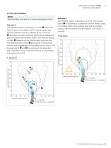
Application software | CAS Functional description 4.2 Use case examples Notice The described use cases 1 to 4 are reversing use cases. The wheeled loader is reversing in a curve. The moving object Use case 1 The wheeled loader is reversing in a curve. field of view for the Radar OHW for typical radar cross sections (detection zone as defined by ISO 21815‑3). illustrates the static nearfield monitoring a parameterizable area behind the wheeled loader. The dynamic driving corridor velocity calls for reaction by the operator. CAS issues a warning. ▼ Use case 2 40 depends on the vehicle speed...
Open the catalog to page 7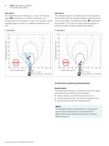
CAS | Application software Functional description The wheeled loader is reversing in a curve. The moving The wheeled loader is in standstill, but the driving direc- tion is reverse and the operator applies a drive command would lead to a collision, and there is not via the drive pedal. The stationary object stopping request to avoid or mitigate the potential colli- the nearfield. CAS issues an active stopping request to avoid any further movement towards this object. enough time for the operator to react. CAS issues an active ν >> 0 km/h Drive direction = REVERSE ν = 0 km/h Drive direction...
Open the catalog to page 8
Application software | CAS Electrical interfaces 5 Electrical interfaces 5.3 Power supplies 5.1 General information The connection diagram for standard wiring is shown in chapter 5.4. A separate document can be provided on Battery power supply ▶ For supply of the RC5-6/40 control unit, 12 V and 24 V batteries are supported. The CAN bus protocol partially follows the definition by ISO 21815‑2 and comprises the following information: ▶ Warning and stopping information ▶ The Radar OHW and the MM7.10 inertial sensor need to be provided with 12 V only. ▶ The RC5-6/40 control unit is using an...
Open the catalog to page 9All Bosch Rexroth Components for Mobile Robotics catalogs and technical brochures
-
Press module for die cushion
24 Pages
-
Accumulator modules
16 Pages
-
BODAS Inertial sensor MM7.10
14 Pages
-
BODAS Pressure sensor PR4
32 Pages
-
Filtermatte
2 Pages


