- Catalogs
- Boreasa Technologies Co., Ltd
- Motor driver with integrated controller D30/5/4QF-E2
- Company
- Products
- Catalogs
- News & Trends
- Exhibitions
Motor driver with integrated controller D30/5/4QF-E2
1 /1Page

Motor driver with integrated controller D30/5/4QF-E2
1 /1Page
Catalog excerpts
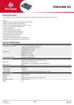
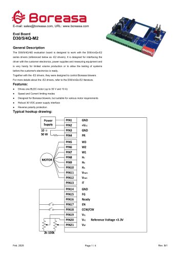
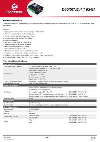
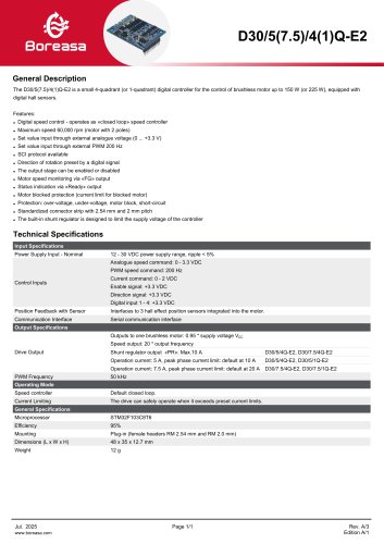
General Description The D30/5/4QF-E2 is a small 4-quadrant digital controller for the control of brushless motor up to 150 W without hall sensors. Features: • Digital speed control - operates as «closed loop» speed controller • Maximum speed 60,000 rpm (motor with 2 poles) • Set value input through external analogue voltage (0 ... +3.3 V) • Set value input through external PWM 200 Hz • FOC with closed-loop torque regulation • Direction of rotation preset by a digital signal • The output stage can be enabled or disabled • Motor speed monitoring via «FG» output • Status indication via «Ready» output • Motor blocked protection (current limit for blocked motor) • Standardized connector strip with 2.54 mm and 2 mm pitch
Open the catalog to page 1All Boreasa Technologies Co., Ltd catalogs and technical brochures
 C55H1-01
3 Pages
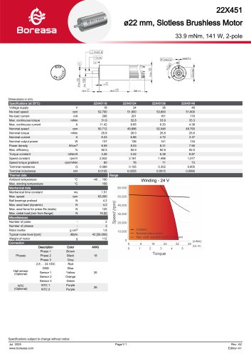 22X451
1 Page
 22X602
1 Page
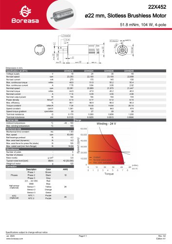 22X452
1 Page
 19X431
1 Page
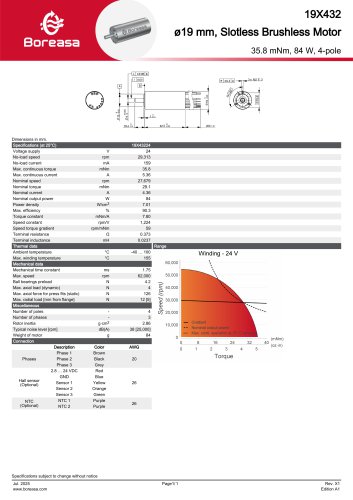 19X432
1 Page
 19X581
1 Page
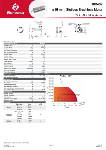 16X402
1 Page
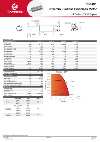 16X401
1 Page
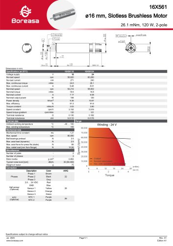 16X561
1 Page
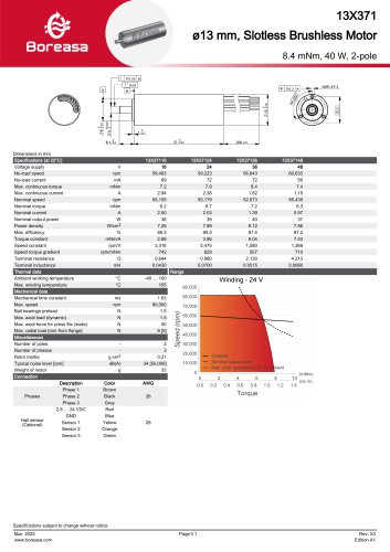 13X371
1 Page
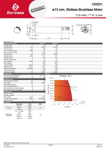 13X531
1 Page
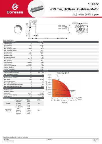 13X372
1 Page
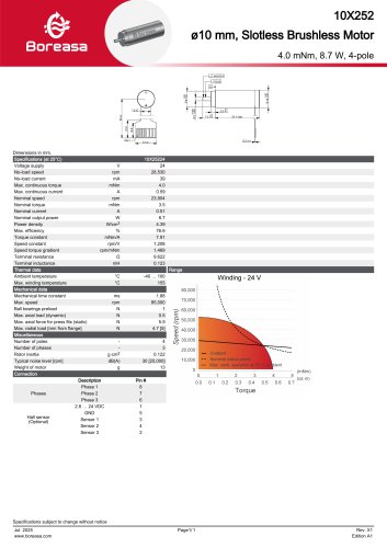 10X252
1 Page
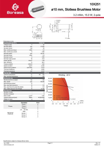 10X251
1 Page
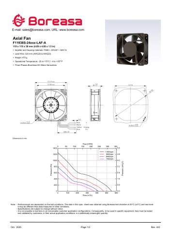 Axial Fan F11938S-246-LP-B
2 Pages
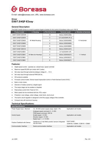 Driver D30-7.5-4QF-E3xay
2 Pages
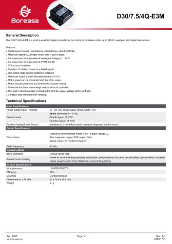 Driver D30/7.5/4QF-E3M
1 Page
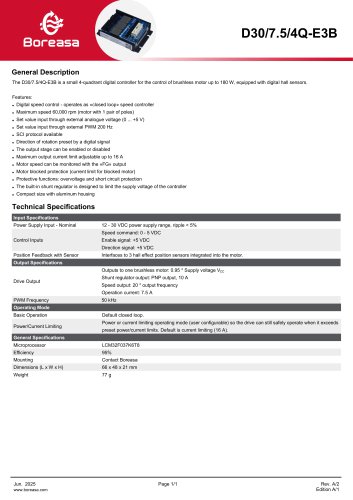 Driver D30/7.5/4QF-E3B
1 Page
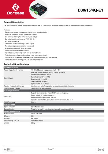 Driver D30/15/4Q-E1
1 Page
 Driver D30/7.5/4Q-E1
1 Page
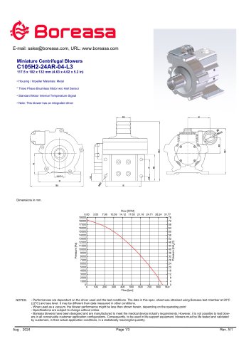 Blower C105H2
3 Pages
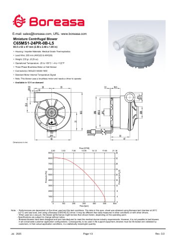
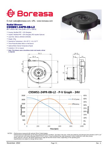 C95MS1-0B
3 Pages
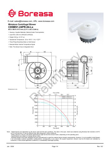 Blower C85MS1-04
4 Pages
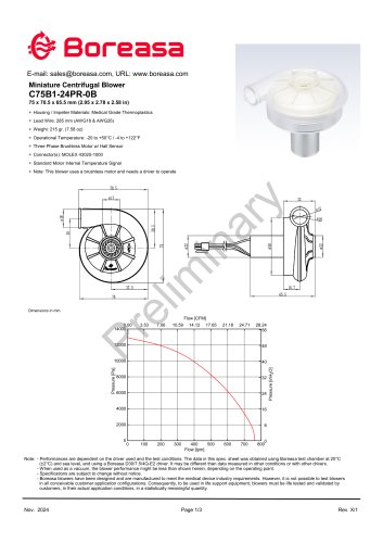 Blower C75B1
3 Pages
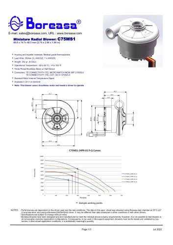 Blower C75MS1-01
3 Pages
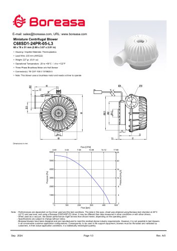 Blower C68SD1
3 Pages
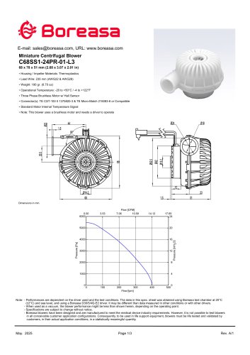 Blower C68SS1
3 Pages
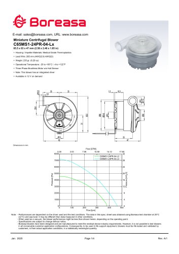
 Blower C65MS1-04
4 Pages
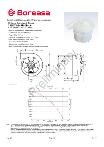 Blower C65DT1
3 Pages
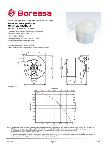 Blower C65D1
3 Pages
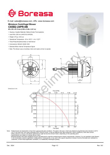 Blower C65B2
3 Pages
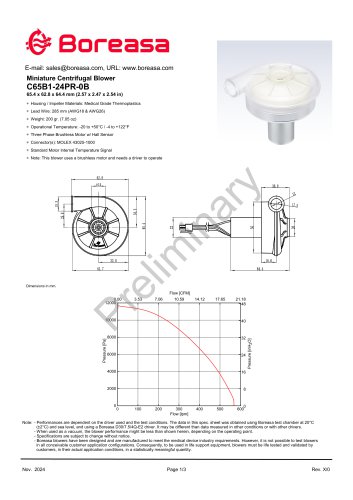 Blower C65B1
3 Pages
 Blower C65S1
3 Pages
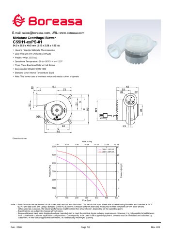 Blower C55H1-01
3 Pages
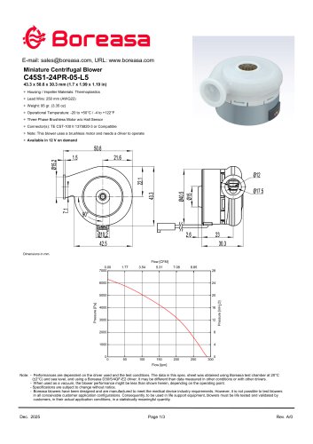 Blower C45S1
3 Pages
 Blower C55H1-04
4 Pages
 Blower C65MS1-24PS-01-L5
3 Pages
 Blower C65MS1
4 Pages
 Blower C65S1
3 Pages
 Small blower C60S1-05-L2
3 Pages
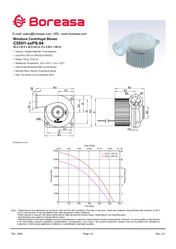
 Small blower C55H1-04
4 Pages
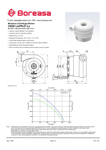
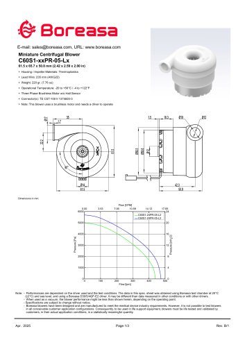
 C60S1
C60S13 Pages