- Catalogs
- Boot and Work Corp, S.L.
- Touchberry 7’’& Tinkertouch 7’’
Touchberry 7’’& Tinkertouch 7’’
1 /43Pages

Touchberry 7’’& Tinkertouch 7’’
1 /43Pages
Catalog excerpts

Touchberry 7’’& Tinkertouch 7’’ User Guide
Open the catalog to page 1
Touchberry 7’’ & TinkerTouch 7’’ User Guide Revised August 20
Open the catalog to page 3
This User Guide is been implemented by Boot & Work, S.L. working under the name Industrial Shields. Purpose of the manual The information contained in this manual can be used as a reference to operating, to functions, and to the technical data of the signal modules, power supply modules and interface modules. Intended Audience This User Guide is intended for the following audience: • • • • Persons in charge of introducing automation devices. Persons who design automation systems. Persons who install or connect automation devices. Persons who manage working automation installation. Unused pins...
Open the catalog to page 4
control room should be limited to authorized personnel. Failure to follow these installation requirements could result in severe personal injury and/or property damage. Always follow these requirements when installing Panel PC. In case of installation or maintenance of the TinkerTouch 7’’ or Touchberry 7’’ please follow the instructions marked in the Installation and Maintenance section. Do not disconnect equipment when a flammable or combustible atmosphere is present. Disconnection of equipment when a flammable or combustible atmosphere is present may cause a fire or explosion which could result...
Open the catalog to page 5
Application Considerations and Warranty Read and Understand this Manual Please read and understand this manual before using the product. Please consult your comments or questions to Industrial Shields before using the product. Application Consideration THE PRODUCTS CONTAINED IN THIS DOCUMENT ARE NOT SAFETY RATED. THEY SHOULD NOT BE RELIED UPON AS A SAFETY COMPONENT OR PROTECTIVE DEVICE FOR ENSURING SAFETY OF PERSONS, AS THEY ARE NOT RATED OR DESSIGNED FOR SUCH PURPOSES. Please know and observe all prohibitions of use applicable to the products. FOR AN APPLICATION INVOLVING SERIOUS RISK TO LIFE...
Open the catalog to page 6
Intended use or of Industrial Shields products Consider the following: Industrial Shields products should only be used for the cases of application foreseen in the catalogue and the associated technical documentation. If third-party products and components are used, they must have been recommended or approved by Industrial Shields. The correct and safe operation of the products requires that your transport, storage, installation, assembly, operation and maintenance have been carried out in a correct It must respect the permissible ambient conditions. You should also follow the indications and...
Open the catalog to page 7
Errors and Omissions The information in this document has been carefully checked and is believed to be accurate; however, no responsibility is assumed for clerical, typographical, or proofreading errors, or omissions. Residual Risks The control and drive components of an Industrial Shields Panel PC are approved for industrial and commercial use in industrial line supplies. Their use in public line supplies requires a different configuration and/or additional measures. These components may only be operated in closed housings or in higher-level control cabinets with protective covers that are closed,...
Open the catalog to page 8
Warranty and Limitations of Liability Warranty Industrial Shields’s exclusive warranty is that the products are free from defects in materials and workmanship for a period of one year (or other period if specified) from date of sale by Industrial Shields. INDUSTRIAL SHIELDS MAKES NO REPRESENTATION OR WARRANTY, EXPRESSED OR IMPLIED, REGARDING MERCHANABILITY, NONINFRINGEMENT, OR FITNESS FOR PARTICULAR PURPOSE OF THE PRODUCTS. ANY BUYER OR USER ACKNOWLEDGES THAT THE BUYER OR USER ALONE HAS DETERMINED THAT THE PRODUCTS WILL SUITABLY MEET THE REQUIREMENTS OF THEIR INTENDED USE. INDUSTRIAL SHIELDS...
Open the catalog to page 9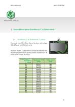
General Description Touchberry 7’’ & Tinkertouch 7’’ Touchberry 7’’ & Tinkertouch 7’’ pinout A compact Panel PC in Open Source Hardware technology. With different Input/Outputs units. Next it is showed a table with the connection between the Raspberry Pi/Tinkerboard pinout and the Touchberry 7’’ & Tinkertouch 7’’Panel PC Pinout. TinkerTouch 7’’ / Touchberry 7’’ Pinout 11 12 13 16 18 22 24 26 29 31 32 33 35 36 37 38 40 Tinker board GPIO
Open the catalog to page 11
Mechanical dimension Panel Touch 7” is designed to be placed build-in an electrical box. Next it is showed the dimensions to be installed properly:
Open the catalog to page 12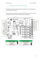
Touchberry 7’’ & Tinkertouch 7’’ pin layout: The following image shows the distribution of the Panel PC pins (in the image you can see the Panel PC from the back). On the right side are the GPIO pins of the Panel PC while the set of pins on the left corresponds to the communication and power pins of the equipment. Touchberry 7’’ & Tinkertouch 7’’ Jumpers Operation: The configuration of the jumpers is explained below. In each configuration the different positions are explained and here you can find a graphic reference to the configuration tables of section 2: Example Jumper 1 VIO = VCOM Enable...
Open the catalog to page 13
Here you are selecting between the two possible configurations that the jumper allows you. Using the Jumper Block you can select in which pins are you allowing the electricity to flow.
Open the catalog to page 14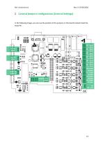
General Jumpers configuration (General Settings) In the following image, you can see the position of the jumpers on the board located inside the Panel PC:
Open the catalog to page 15
General Jumper Configuration. Left zone (General settings): Named from top to bottom: Left Jumper 3 SPI 3.3 V Enable 3 SPI 5V Left Jumper 4 enables SPI at 3.3V or 5V. Typical configurations showed below: Left Jumper 3 SPI 3.3 V Enable 3 SPI 5V Left Jumper 3 SPI 3.3 V Enable 3 SPI 5V This configuration enables SPI at 3.3V. This configuration enables SPI at 5V. Left Jumper 4 enables I2C at 3.3V or 5V. Typical configurations showed below: Left Jumper 4 I2C 3.3 V Enable 4 I2C 5V This configuration enables I2C at 3.3V. This configuration enables I2C at 5V. Left Jumper 5 RS-485 Half Duplex 15
Open the catalog to page 16All Boot and Work Corp, S.L. catalogs and technical brochures
 Spartan Arduino PLC 21+
3 Pages
 M-Duino 19R+ LoRa
4 Pages
 M-Duino 38AR+ DALI
3 Pages
 PLC 16RDA
3 Pages
 DatasheetM-Duino 50RRA+ GPRS
3 Pages
 SPARTANS
4 Pages


- Electromotor
- Connector
- DC power supply
- Industrial panel PC
- Panel PC with touch screen
- AC/DC power supply
- Data connector
- LCD panel PC
- Angular encoder
- Linux panel PC
- Round connector
- Incremental encoder
- Socket electrical connector
- Industrial connector
- Junction block
- Circular connector
- Wireless panel PC
- Single-output power supply