
- Catalogs
- Bonfiglioli
- VF-W series - Wormgears


VF-W series - Wormgears

VF-W series - Wormgears
- Symbols and Units of Measurement: The document defines symbols such as torque (M), power (P), and efficiency (η), along with their units.
- Definitions: Key terms like rated torque, required torque, and calculated torque are explained, emphasizing their importance in gearbox selection.
- Allowed Temperature Limits: Operational temperature ranges for components are specified, highlighting material selection for extreme conditions.
- Design Features: Structural characteristics of wormgears, including efficiency and load handling capabilities, are described.
- Versions and Arrangements: Different configurations and mounting options for gearboxes are detailed.
- Gearbox Options: Additional features and customizations for gearboxes are listed.
- Main Benefits: Advantages of the EP series, particularly for the food and beverage industries, due to enhanced corrosion protection.
- General Characteristics: Overview of mechanical and electrical features, including brake systems and motor options.
- Selection Process: Steps for selecting a gearmotor, including determining the service factor and required power.
- Installation and Lubrication: Guidelines for proper installation and maintenance to ensure optimal performance and longevity.
Catalog excerpts

We have a relentless commitment to excellence, innovation and sustainability. Our team creates, distributes and services world-class power transmission and drive solutions to keep the world in motion. PRODUCT HEADQUARTERS Bonfiglioli Riduttori S.p.A. Via Giovanni XXIII, 7/A 40012 Lippo di Calderara di Reno Bologna (Italy) tel: +39 051 647 3111 fax: +39 051 647 3126 [email protected] www.bonfiglioli.com
Open the catalog to page 1
GENERAL INFORMATION VF-EP / W-EP - GEARBOXES AND GEARMOTORS FOR CORROSIVE AND ASEPTIC ENVIRONMENTS protection) series for the food and beverage industries 32 Designation 184 35 Others information about gearbox 187 22 Speed reducer rating charts 73 23 Ratio distribution for VF/VF, VF/W, W/VF 95 26 Dimensions for gearmotors an gear units 111 with IEC motor interface. 27 DImensions for gear units with solid 27 input shaft 28 Accessories 29 Customer' shaft 30 Torque limiter ELECTRIC MOTORS M6 DC brake motors type BN and M_FD 216 M7 AC brake motors type BN and M_FA 220...
Open the catalog to page 3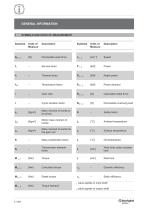
GENERAL INFORMATION
Open the catalog to page 4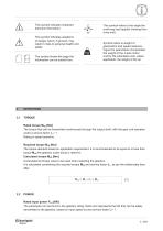
This symbol indicates important technical information. This symbol refers to the angle the overhung load applies (viewing from drive end). This symbol indicates situations of danger which, if ignored, may result in risks to personal health and safety. The symbol shows the page the information can be sorted from. Symbol refers to weight of gearmotors and speed reducers. Figure for gearmotors incorporates the weight of the 4-pole motor and for life lubricated units, where applicable, the weight of the oil. TORQUE Rated torque Mn2 [Nm] The torque that can be transmitted continuously through the...
Open the catalog to page 5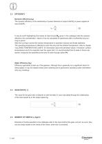
EFFICIENCY Dynamic efficiency [ηd] The dynamic efficiency is the relationship of power delivered at output shaft P2 to power applied at input shaft P1: d It may be worth highlighting that values of rated torque Mn2 given in the catalogue take the dynamic efficiency into consideration. Values of ηd are calculated for gearboxes after a sufficiently long running-in period. After the running-in period the surface temperature in operation reduces and finally stabilises. The operating temperature is affected by both the duty and the ambient temperature, refer to chapter “ALLOWED TEMPERATURE LIMITS”...
Open the catalog to page 6
This factor is the numeric value describing reducer service duty. It takes into consideration, with unavoidable approximation, daily operating conditions, load variations and overloads connected with reducer application. In the graph below, after selecting proper “daily working hours” column, the service factor is given by intersecting the number of starts per hour and one of the K1, K2 or K3 curves. K_ curves are linked with the service nature (approximately: uniform, medium and heavy) through the acceleration factor of masses K, connected to the ratio between driven masses and motor inertia...
Open the catalog to page 7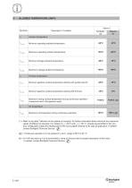
(*) = Refer to the table “Selection of the optimal oil viscosity” for further information about minimum and maximum values of different oil viscosity. For values of ta < -20°C and ts, to > 80 °C, choose (as permitted in the product configuration stage) the sealing type of the most suitable material to the type of application. If needed contact Bonfiglioli Technical Service. © (@) = Continuous operation it is not advised if ts and to range is 80°C to 95 °C. provide for greater absorption of the motor. (#) = For full load start-up it is recommended to ramp-up and If needed, contact Bonfiglioli...
Open the catalog to page 8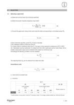
a) Determine service factor fs as formerly specified. b) Determine power required at gearbox input shaft: [kW] (5) c) Consult the gearmotor rating charts and locate the table corresponding to normalised power Pn: Unless otherwise specified, power Pn of motors indicated in the catalogue refers to continuous duty S1. For motors used in conditions other than S1, the type of duty required by reference to CEI 2-3/IEC 34-1 Standards must be mentioned. For duties from S2 to S8 in particular and for motor frame 132 or smaller, extra power output can be obtained with respect to continuous duty. Accordingly...
Open the catalog to page 9
Next, refer to the appropriate Pn section within the gearmotor selection charts and locate the unit that features the desired output speed n2, or closest to, along with a safety factor S that meets or exceeds the applicable service factor fs. The safety factor is so defined: As standard, gear and motor Combinations are implemented with 2, 4 and 6 pole motors, 50 Hz supplied. Should the drive speed be different from 2800, 1400 or 900 min-1, base the selection on the gear unit nominal rating. Selecting a speed reducer a) Determine service factor fs. b) Determine the computational torque Mc2: c)...
Open the catalog to page 10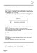
5 VERIFICATION After the selection of the speed reducer, or gearmotor, is complete it is recommended that the following verifications are Conducted: a) Maximum torque The maximum torque (intended as instantaneous peak load) applicable to the gearbox must not, in general, exceed 150% of rated torque Mn2. Upon evaluation and approval of Bonfiglioli Technical Service peak values up to 300% may be admitted. For three-phase switch-pole motors, it is recommended to pay attention to the switching torque which is generated when switching from high to low speed, because it could be significantly higher...
Open the catalog to page 11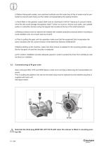
b) Before being paint coated, any machined surfaces and the outer face of the oil seals must be protected to prevent paint drying out the rubber and jeopardising the sealing function. c) Parts fitted on the gearbox output shaft must be machined to ISO H7 tolerance to prevent interference fits that could damage the gearbox itself. Further, to mount or remove such parts, use suitable pullers or extraction devices using the tapped hole located at the top of the shaft extension. d) Mating surfaces must be cleaned and treated with suitable protective products before mounting to avoid oxidation and,...
Open the catalog to page 12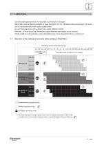
Life lubricated gearboxes do not require any periodical oil changes. Refer to the User’s Manual available at www.bonfiglioli.com for indications about checking the oil level and its replacement for other types of gearboxes. Do not mix mineral oils with synthetic oils and/or different brands. However, oil level should be checked at regular intervals and topped up as required. Check monthly if unit operates under intermittent duty, more frequently if duty is continuous. 7.1 Selection of the optimal oil viscosity (data relating to Shell Oils) Operating ambient temperature [C° I | Recommended operating...
Open the catalog to page 13All Bonfiglioli catalogs and technical brochures
 Product Range Wind Solutions
28 Pages
 Solutions for Packaging
16 Pages
 Solution Condtruction Industry
52 Pages
 Product Range Mobile Solution
44 Pages
 Marine and Offshore
20 Pages
 HDP
HDP88 Pages
 Worm Gear Series
86 Pages
 V series Motovariator
362 Pages
 Mobile Solutions Product Range
44 Pages
 Wind Solutions
24 Pages
 Mechatronic Life Cycle
4 Pages
 Bonfiglioli Digital Tools
12 Pages
 Wind Solutions Product Range
28 Pages
 Solutions for Water Treatment
16 Pages
 Solutions for Food & Beverage
20 Pages
 Spare parts list W Series
24 Pages
 Drives for Road Machinery
36 Pages
 Drives for Excavators
24 Pages
 Solutions for access platforms
16 Pages
 Solutions for Mining
20 Pages
 Solutions for Intralogistics
8 Pages
 VF-W series - Wormgears IE2-IE3
298 Pages
 VF-W series - Wormgears - Atex
46 Pages
 Modular planetary gearboxes
560 Pages
 600W2/3 Series
2 Pages
 610X Series
2 Pages
 Wheel drives - 600 Series
2 Pages
 600Y3 Series
2 Pages
 Widest Range of Final Drive
2 Pages
 600W series
2 Pages
 Active Cube 7
2 Pages
 Power Drive VCB400
16 Pages
 Advanced Standard Drive - Agile
52 Pages
 Solution Drive - Active Series
72 Pages
 BC - DC electric motors
20 Pages
 3/H Combined gearboxes
20 Pages
 RAN series - Mitre gears
28 Pages


- Synchronous motor
- Alternating current motor
- Multipole motor
- Electric gearmotor
- Asynchronous motor
- Planetary gearbox
- Coaxial gearhead
- Electromotor for industrial applications
- Three-phase motor
- Precision gearhead
- Servo-motor
- Right angle gearhead
- Direct current gear-motor
- Compact gearhead
- Solid-shaft gearhead
- Compact electromotor
- IP55 motor
- Hollow-shaft gearhead