- Catalogs
- Bonfiglioli
- VF-W series - Wormgears - Atex
VF-W series - Wormgears - Atex
1 /46Pages

VF-W series - Wormgears - Atex
1 /46Pages
Catalog excerpts

We have a relentless commitment to excellence, innovation and sustainability. Our team creates, distributes and services world-class power transmission and drive solutions to keep the world in motion. PRODUCT HEADQUARTERS Bonfiglioli Riduttori S.p.A. Via Giovanni XXIII, 7/A 40012 Lippo di Calderara di Reno Bologna (Italy) tel: +39 051 647 3111 fax: +39 051 647 3126 [email protected] www.bonfiglioli.com
Open the catalog to page 1
SUMMARY Chapter Page 1.2.2 European harmonised ATEX standards 4 1.2.3 Levels of protection for the various categories of equipment 5 1.4.2 Selecting a gear unit with IEC motor fitting 7 1.4.3 Selecting a speed reducer with solid input shaft 8 1.4.5 Operating conditions for ATEX-specified equipment 8 2 WORM GEAR UNITS FOR POTENTIALLY EXPLOSIVE ATMOSPHERES 10 2.10.2 VF-interchangeable foot kits KA, KV 39 Revisions Refer to page 42 for the catalogue revision index. Visit www.bonfiglioli.com to search for catalogues with up-to-date revisions.
Open the catalog to page 3
1 GENERAL INFORMATION 1.1 S YMBOLS AND UNITS OF MEASURE An [N] The admissible thrust load represents the force which can be applied axially to the gear unit’s shaft, along with the rated radial load. fs - The service factor is a coefficient representing the severity of the duty for the operating cycle. f - The adjusting factor takes into account the influence of the ambient temperature in calculating the computational torque. This factor is relevant for worm gear units. i - The gear ratio is expressed as the relationship of the input shaft speed to the output...
Open the catalog to page 4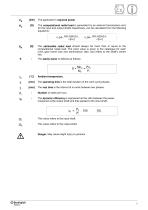
P [kW] The application’s required power. Rc [N onal radial load is generated by an external transmission and, for the input and output shafts respectively, can be calculated from the following equations: Rn [N] The admissible radial load should always be more than or equal to the computational radial load. The point value is given in the catalogue for each unit’s gear frame size and transmission ratio, and refers to the shaft’s centre line. S - The safety factor is defined as follows: g _ Mn2 _ Pn-, "m7 ”pT [°C] Ambient temperature. [min] The operating time is the total duration...
Open the catalog to page 5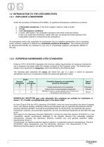
1.2 INTRODUCTION TO THE ATEX DIRECTIVES 1.2.1 EXPLOSIVE A TMOSPHERE Under the provisions of Directive 2014/34/EU, an explosive atmosphere is defined as a mixture: a. of flammable substances, in the form of gases, vapours, mists or dusts; c. under atmospheric conditions; d. in which, after ignition, the combustion spreads to the entire unburned mixture (it has to be noted that sometimes, mainly with dust, not always the whole quantity of the combustible material is consumed by the combustion). An atmosphere which may potentially be transformed into an explosive atmosphere due to operating and/or...
Open the catalog to page 6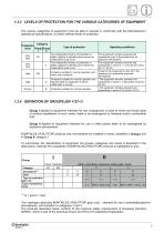
1.2.3 LEVELS OF PROTECTION FOR THE VARIOUS CATEGORIES OF EQUIPMENT The various categories of equipment must be able to operate in conformity with the Manufacturer’s operational specifications, at certain defined levels of protection. This catalogue describes BONFIGLIOLI RIDUTTORI gear units , intended for use in potentiallyexplosive atmospheres, with limitation to categories 2 and 3. The products described herein conform to the minimum safety requirements of European Directive 94/9/EC, which is part of the directives known as ATEX (ATmospheres EXplosibles).
Open the catalog to page 7
1.2.5 DECLARATION OF CONFORMITY The Declaration of Conformity, is the document which attests to the conformity of the product to Directive 2014/34/EU. The validity of the Declaration is bound to observance of the instructions given in the User, Installation and Service Manual for safe use of the product throughout its service life. This can be downloaded from www.bonfiglioli.com where the manual is available in PDF format in a number of languages. The instructions regarding ambient conditions are of particular importance inasmuch as failure to observe them during operation of the product renders...
Open the catalog to page 8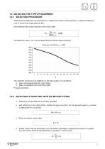
1.4 SELECTING THE TYPE OF EQUIPMENT 1.4.1 SELECTION PROCEDURE: Determine the application service factor fS in relation to the type of load (K factor), number of starts per hour Zr and hours of operation per day. Now determine the power required at the motor shaft: The efficiency value « ηd » can be determined as follows (approximately): Worm gear unit efficiency - n1=1400 The selection procedure now depends on the type of gear unit, as follows: a. gear unit equipped with IEC motor fitting b. gear unit equipped with solid input shaft. Proceed as follows: 1.4.2 SELECTING A GEAR UNIT WITH IEC MOTOR...
Open the catalog to page 9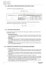
1.4.3 SELECTING A SPEED REDUCER WITH SOLID INPUT SHAFT - Calculate the value of the computational torque: - for the speed n2 closest to that required, select the gear unit with a rated torque Mn2 equal to or greater than the computational torque Mc2, in other words: 1.4.4 POST-SELECTION CHECKS Once the gear unit or the gear unit with IEC motor fitting has been selected, we recommend checkin the selection as follows: • Momentary peak torque The momentary peak torque is of the order of 200% of the rated torque Mn2. Check that the point value of the peak torque satisfies this condition and equip...
Open the catalog to page 10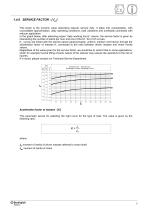
1.4.6 SERVICE FACTOR - [ fs ] This factor is the numeric value describing reducer service duty. It takes into consideration, with unavoidable approximation, daily operating conditions, load variations and overloads connected with reducer application. In the graph below, after selecting proper “daily working hours” column, the service factor is given by intersecting the number of starts per hour and one of the K1, K2 or K3 curves. K_ curves are linked with the service nature (approximately: uniform, medium and heavy) through the acceleration factor of masses K, connected to the ratio between driven...
Open the catalog to page 11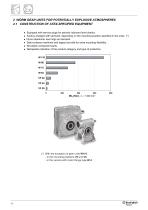
2 WORM GEAR UNITS FOR POTENTIALLY EXPLOSIVE ATMOSPHERES 2.1 CONSTRUCTION OF ATEX-SPECIFIED EQUIPMENT • Equipped with service plugs for periodic lubricant level checks. • Factory-charged with lubricant, depending on the mounting position specified in the order. (*) • Fluoro elastomer seal rings as standard. • Side surfaces machined and tapped provide for extra mounting flexibility. • No plastic component parts. • Nameplate indication of the product category and type of protection. (*) With the exception of gear units W110: - in the mounting positions V5 and V6 - in the version with motor flange...
Open the catalog to page 12All Bonfiglioli catalogs and technical brochures
 Product Range Wind Solutions
28 Pages
 Solutions for Packaging
16 Pages
 Solution Condtruction Industry
52 Pages
 Product Range Mobile Solution
44 Pages
 Marine and Offshore
20 Pages
 HDP
HDP88 Pages
 Worm Gear Series
86 Pages
 V series Motovariator
362 Pages
 Mobile Solutions Product Range
44 Pages
 Wind Solutions
24 Pages
 Mechatronic Life Cycle
4 Pages
 Bonfiglioli Digital Tools
12 Pages
 Wind Solutions Product Range
28 Pages
 Solutions for Water Treatment
16 Pages
 Solutions for Food & Beverage
20 Pages
 Spare parts list W Series
24 Pages
 Drives for Road Machinery
36 Pages
 Drives for Excavators
24 Pages
 Solutions for access platforms
16 Pages
 Solutions for Mining
20 Pages
 Solutions for Intralogistics
8 Pages
 VF-W series - Wormgears IE2-IE3
298 Pages
 VF-W series - Wormgears
268 Pages
 Modular planetary gearboxes
560 Pages
 600W2/3 Series
2 Pages
 610X Series
2 Pages
 Wheel drives - 600 Series
2 Pages
 600Y3 Series
2 Pages
 Widest Range of Final Drive
2 Pages
 600W series
2 Pages
 Active Cube 7
2 Pages
 Power Drive VCB400
16 Pages
 Advanced Standard Drive - Agile
52 Pages
 Solution Drive - Active Series
72 Pages
 BC - DC electric motors
20 Pages
 3/H Combined gearboxes
20 Pages
 RAN series - Mitre gears
28 Pages


- Electromotor
- Synchronous motor
- Alternating current motor
- Multipole motor
- Electric gearmotor
- Asynchronous motor
- Planetary gearbox
- Coaxial gearhead
- Electromotor for industrial applications
- Three-phase motor
- Precision gearhead
- Right angle gearhead
- Direct current gear-motor
- Compact gearhead
- Servo-motor
- 4-pole motor
- Solid-shaft gearhead
- IP55 motor
- Compact electromotor
- Gear train gear reducer