- Catalogs
- Bonfiglioli
- Helical and bevel-helical gear units C-A-F Series - NORTH AMERICA EDITION
Helical and bevel-helical gear units C-A-F Series - NORTH AMERICA EDITION
1 /684Pages

Helical and bevel-helical gear units C-A-F Series - NORTH AMERICA EDITION
1 /684Pages
Catalog excerpts

We have a relentless commitment to excellence, innovation and sustainability. Our team creates, distributes and services world-class power transmission and drive solutions to keep the world in motion. C-A-F series - NORTH AMERICA EDITION Helical gear units C Helical bevel gear units A Shaft mounted gear units F HEADQUARTERS Bonfiglioli Riduttori S.p.A. Via Giovanni XXIII, 7/A 40012 Lippo di Calderara di Reno • Bologna (Italy) tel: +39 051 647 3111 • fax: +39 051 647 3126 [email protected] • www.bonfiglioli.com NORTH AMERICA EDIT
Open the catalog to page 1
Chapter Description Page Chapter Description Page SHAFT MOUNTED GEAR UNITS SERIES F 416 HELICAL GEAR UNITS SERIES C 22 22 Mounting position and terminal box 29 HELICAL BEVEL GEAR UNITS SERIES A 202 49 Mounting position and terminal box 423 ELECTRIC MOTORS M8 DC brake motors type BN_FD and M_FD 621 M9 AC brake motors type BN_FA and M_FA 625 M13 Motor rating charts BX-MX 639 M15 Motor rating charts BE-ME 646 M17 Motor rating charts BN-M 656 34 Mounting position and terminal box 210 Revisions Refer to page 680 for the catalogue...
Open the catalog to page 3
1 SYMBOLS AND UNITS OF MEASURE Symbols Units of Description Measure Symbols Units of Description Measure Output shaft angular 9 [’] backlash (with locked input shaft) value applies to input shaft value applies to output shaft
Open the catalog to page 4
The symbol shows the page the information can be sorted from. This symbol refers to the angle the overhung load applies (viewing from drive end). IMPORTANT This symbol indicates important technical information. Symbol refers to weight of gearmotors and speed reducers. Figure for gearmotors incorporates the weight of the 4-pole motor and for life lubricated units, where applicable, the weight of the oil. Gearmotor with compact motor. Gearmotor with IEC motor. Gear unit with IEC motor interface. Gear unit with NEMA motor interface. Gear unit with servomotor input adapter. Speed reducer with solid...
Open the catalog to page 5
(*) = Refer to the table “Selection of the optimal oil viscosity” for further information about minimum and maximum values of different oil viscosity. For values of ta < -20°C [+70°F] and ts, to > 80 °C [+176°F], choose (as permitted in the product configuration stage) the sealing type of the most suitable material to the type of application. If needed contact Bonfiglioli Technical Service. © (@) = Continuous operation it is not advised if ts and to range is 80°C [+176°F] to 95 °C [+203°F]. provide for greater absorption of the motor. (#) = For full load start-up it is recommended to ramp-up...
Open the catalog to page 6
3.1 Rated torque Tn2 [lb»in] The torque that can be transmitted continuously through the output shaft, with the gear unit operated under a service factor fs = 1. Rating is speed sensitive. The torque demand based on application requirement. It must always be equal to or less than torque Tn2 the gearbox under study is rated for. Computational torque value to be used when selecting the gearbox. It is calculated considering the required torque Tr2 and service factor fs , as per the equation here after: 4.1 Rated power Pn1 [hp] In the gearbox selection charts this is the power applicable to input...
Open the catalog to page 7
Gear units featuring more than 2 reductions and/or a gear ratio greater than i = 45 do not normally require the thermal limit to be checked as in these cases the thermal rating usually exceeds the mechanical rating. (A 1)
Open the catalog to page 8
©Bonfiglioli Riduttori
Open the catalog to page 9
GEAR RATIO i The value for the gear ratio is referred to with the letter [ i ] and calculated through the relationship of the input speed n1 to the output speed n2: The gear ratio is usually a decimal number which in this catalogue is truncated at one digit after the comma (no decimals for i > 1000). If interested in knowing the exact value see also chapters “EXACT RATIOS”. ANGULAR VELOCITY Input speed n1 [rpm] The speed is related to the prime mover selected. Catalogue values refer to speed of single speed motors that are common in the industry. If the gearbox is driven by an external transmission...
Open the catalog to page 10
SERVICE FACTOR fs This factor is the numeric value describing reducer service duty. It takes into consideration, with unavoidable approximation, daily operating conditions, load variations and overloads connected with reducer application. In the graph (A4) below, after selecting proper “daily working hours” column, the service factor is given by intersecting the number of starts per hour and one of the K1, K2 or K3 curves. K_ curves are linked with the service nature (approximately: uniform, medium and heavy) through the acceleration factor of masses K, connected to the ratio between driven masses...
Open the catalog to page 11
Service factors listed here under are empirical values based on AGMA and ISO specifications as well as our experience for use in common applications. They apply for state of the art-designed driven machines and normal operating conditions. (*) - Indication of service factor based on FEM 1.001 classification available upon request. Consult factory. - Hoists for passengers lift: charted values not applicable. Consult factory.
Open the catalog to page 12
(*) - Indication of service factor based on FEM 1.001 classification available upon request. Consult factory. - Hoists for passengers lift: charted values not applicable. Consult factory. ©BonFiglioli Riduttori
Open the catalog to page 13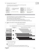
10.1 Acceleration factor of masses K This parameter serves for selecting the right curve for the type of load. The value is given by the following ratio: | | Recommended operating limits i i Allowed operating limits. © Forbidden operating limits. * = It is recommended to ramp-up and to provide for greater absorption of the motor. If needed and in the event of impulse loads, contact Bonfiglioli Technical Service. © ©Bonfiglioli Riduttori
Open the catalog to page 15
11.2 Lubrication for C, A, F, S series gearboxes The inner parts of Bonfiglioli gear units are oil-bath and splash lubricated. Frame sizes C 05...C 41, A 05...A 41, F 10...F 41 are supplied by the factory, or by the authorized dealers, already filled with oil. Unless otherwise specified, units size C 51, A 50, F 51 and larger are usually supplied unlubricated at it will be the customer care to fill them with oil prior to putting them into operation. In both cases, depending on the version, prior to putting the gear unit into operation may need to replace the closed plug used for transportation...
Open the catalog to page 16All Bonfiglioli catalogs and technical brochures
 Product Range Wind Solutions
28 Pages
 Solutions for Packaging
16 Pages
 Solution Condtruction Industry
52 Pages
 Product Range Mobile Solution
44 Pages
 Marine and Offshore
20 Pages
 HDP
HDP88 Pages
 Worm Gear Series
86 Pages
 V series Motovariator
362 Pages
 Mobile Solutions Product Range
44 Pages
 Wind Solutions
24 Pages
 Mechatronic Life Cycle
4 Pages
 Bonfiglioli Digital Tools
12 Pages
 Wind Solutions Product Range
28 Pages
 Solutions for Water Treatment
16 Pages
 Solutions for Food & Beverage
20 Pages
 Spare parts list W Series
24 Pages
 Drives for Road Machinery
36 Pages
 Drives for Excavators
24 Pages
 Solutions for access platforms
16 Pages
 Solutions for Mining
20 Pages
 Solutions for Intralogistics
8 Pages
 VF-W series - Wormgears IE2-IE3
298 Pages
 VF-W series - Wormgears - Atex
46 Pages
 VF-W series - Wormgears
268 Pages
 Modular planetary gearboxes
560 Pages
 600W2/3 Series
2 Pages
 610X Series
2 Pages
 Wheel drives - 600 Series
2 Pages
 600Y3 Series
2 Pages
 Widest Range of Final Drive
2 Pages
 600W series
2 Pages
 Active Cube 7
2 Pages
 Power Drive VCB400
16 Pages
 Advanced Standard Drive - Agile
52 Pages
 Solution Drive - Active Series
72 Pages
 BC - DC electric motors
20 Pages
 3/H Combined gearboxes
20 Pages
 RAN series - Mitre gears
28 Pages


- Synchronous motor
- Alternating current motor
- Multipole motor
- Electric gearmotor
- Asynchronous motor
- Planetary gearbox
- Coaxial gearhead
- Electromotor for industrial applications
- Three-phase motor
- Precision gearhead
- Right angle gearhead
- Direct current gear-motor
- Compact gearhead
- Solid-shaft gearhead
- IP55 motor
- Gear train gear reducer