


HDP

HDP
- Symbols and Units of Measurement: The document lists symbols and units such as torque (T), speed (n), and horsepower (P).
- Product Features: HDP gear units are noted for high torque density, performance, and reliability, with customizable options. They come in various sizes and reduction stages, featuring rigid housing and helical gears.
- Installation: Guidelines include securing the gearbox to prevent vibrations, protecting surfaces before painting, and ensuring correct oil levels and viscosity.
- Maintenance: An initial lubricant change is recommended after 300 hours, with different oil change intervals based on temperature and oil type.
- Storage: Gear units should be stored indoors, protected from weather, and coated with rust inhibitors for long-term storage.
- Conditions of Supply: Gear units are supplied configured for specific mounting positions and tested to manufacturer specifications.
- Paint Coating: Gearboxes are painted with epoxy resin and polyester powder for corrosion protection, suitable for outdoor installations.
- Service Factor: Empirical values based on AGMA and ISO specifications indicate the robustness required for different operational conditions.
- Lubrication: Gearboxes use a mixed immersion and splash system, with specific lubrication systems required for certain mounting positions.
- Engineering Selection: Guidelines for selecting the appropriate gear unit based on application requirements.
- Verifications: Steps to verify the selected gear unit meets necessary specifications.
- Sample Application: Example scenarios illustrate the selection process.
- Base and Optional Variants: Describes different configurations available, including mounting positions and input/output configurations.
- Permitted Loads: Charts detail allowed overhung and thrust loads on output shafts.
- Mass Moment of Inertia and Exact Ratios: Provides data for precise engineering calculations.
- Mounting and Manifold Flanges: Specifications for different flange types and customer shaft requirements.
1. Determine the gear ratio by dividing the input speed by the output speed.
2. Calculate the required horsepower at the input shaft using the provided formula.
3. Identify the applicable service factor and adjusting factor based on the prime mover type.
4. Use rating charts to select a gear unit with a gear ratio close to the calculated one and ensure the rated horsepower meets the required conditions.
Shock Loading: Ensure momentary peak torque does not exceed specified limits. Consider a torque limiter if necessary.
Motor Mounting: Verify that the electric motor does not exceed the required power during operation.
Lubrication: Pre-heat lubricant if operating in low temperatures or if oil viscosity is high.
Backstop Device: Check load capacity and ensure torque does not exceed limits.
Overhung Load: Calculate and verify that shaft loading is within permissible limits.
Calculate the thermal capacity to ensure the gearbox can operate without overheating. Consider additional cooling options if necessary.
Various configurations are available, including different mounting positions, input configurations, shaft arrangements, and gear ratios. Optional variants include certificates, mounting devices, sensors, oil sealing, reinforced bearings, and auxiliary thermal devices.
Tables provide data on factors affecting thermal capacity, overhung load verification, and permissible loads based on different conditions and configurations.
The document outlines various mounting positions for gear units, emphasizing flexibility in configuration to suit different operational needs.
The gear unit can be configured with a solid input shaft, either single- or double-sided. Motor mounting options include flanges, scoops, top mounts, and baseplates. Shaft arrangements are customizable.
- Auxiliary Cooling Devices: Options include fan cooling, cooling coils, and independent cooling units. Fan cooling is available for specific HDP models, with configurations for single or dual fans. Cooling coils require integration into a water supply circuit with specified parameters. Independent cooling units use either water/oil or air/oil heat exchangers.
- Heaters: Electrical heating elements can be installed for low ambient temperatures, requiring thermostat wiring by the installer.
- Forced Lubrication: Available for continuous and intermittent duty applications, with mechanical or motor pump options depending on the drive speed and configuration.
- Backstop Device: Prevents backdriving of the gearbox, with specifications for torque and direction of free rotation.
- Reinforced Bearings: Heavy-duty bearings are available for increased load capacity, applicable to specific models and configurations.
- Seals and Gaskets: Various oil sealing systems are available, including Taconite, Viton, and dual seal options.
- Sensors: Options include bimetal thermostats for temperature detection and oil level indicators for remote monitoring.
- Drywell: Ensures proper sealing for the output shaft, requiring a forced lubrication system.
Certificates of compliance, inspection, and type are available, detailing checks on order compliance, visual inspections, and functional parameters.
Charts provide detailed ratings for various HDP models, including torque, power, and load specifications at different speeds.
The document provides detailed specifications for various HDP models, including dimensions, tolerances, and weight. The bore shaft dimensions are specified with tolerances for different diameter ranges, indicating precise engineering requirements.
Instructions are given for mounting flanges and customer shafts, including dimensions and configurations for different HDP models. The document also outlines procedures for handling external thrust loads and securing shafts to prevent accidental decoupling.
The document references standards such as UNI6604, UNI7437, and UNI5739, likely related to mechanical and engineering specifications.
Recommendations include installing suitable devices to secure shafts in the presence of external thrust loads, vibrations, or unfavorable mounting positions to enhance reliability and safety.
Tables provide exact ratios, dimensions, and weights for HDP models ranging from HDP 60 to HDP 140. Key data includes bore shaft tolerances, mounting flange dimensions, and customer shaft specifications.
Emphasis is placed on the importance of adhering to specified tolerances and dimensions to ensure proper function and safety. The document also highlights the need for modifications to be implemented without notice, indicating a dynamic approach to product updates.
Catalog excerpts
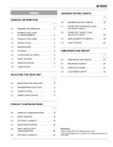
GEARBOX RATING CHARTS GEARBOX RATING CHARTS . . . . . . . . . . 32 PERMITTED OVERHUNG LOADS ON OUTPUT SHAFT . . . . . . . . . . . . . . . . . 41 SYMBOLS AND UNITS OF MEASUREMENT . . . . . . . . . . . . . . . . . . 2 PERMITTED THRUST LOAD ON OUTPUT SHAFT . . . . . . . . . . . . . . . . . 50 MASS MOMENT OF INERTIA . . . . . . . . . . 59 SELECTING THE GEAR UNIT SELECTING THE GEAR UNIT . . . . . . . . . . . 8 PRODUCT CONFIGURATIONS INPUT AND OUTPUT CONFIGURATION . . . . . . . . . . . . . . . . . . . 20 Revisions Refer to page 84 for the catalog revision index. Visit www.bonfiglioli.com to search...
Open the catalog to page 3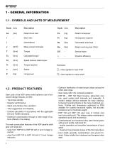
BONFIGLIOLI RIDUTTORI 1 - GENERAL INFORMATION 1.1 - SYMBOLS AND UNITS OF MEASUREMENT Description Rated thrust load Gear ratio Intermittence Mass moment of inertia Torque Calculated torque Speed reducer rated torque Torque required Speed Horsepower Description Rated horsepower Horsepower required Calculated radial load Rated overhung load (OHL) Service factor Dynamic efficiency Footnotes: □ i value applies to input shaft D2 value applies to output shaft 1.2 - PRODUCT FEATURES Gear units of the HDP series make optimum use of advanced design features, to offer: • Top torque density. • Superior performance. •...
Open the catalog to page 4
• Input shaft configurations: - HDP 60 ... HDP 140: solid, single or double-sided shaft with dimensions to UNI/ISO 775-88 (extended length) • Output shaft configurations: - solid, single or double-sided shaft with dimensions to UNI/ISO 775-88 (extended length) - hollow shaft with keyway - hollow shaft with shrink disc • Heavy duty taper roller bearings or extra large self-aligning roller bearings from the premium suppliers brands for unparalleled overhung load capacity. • A wide range of customization options are available upon request, including: - auxiliary cooling/heating devices - forced...
Open the catalog to page 5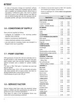
• In case of long-term storage all machined surfaces such as flanges, shafts and couplings must be coated with a suitable rust inhibiting product (Shell Ensis or equivalent). Furthermore gear units must be placed with the fill plug in the highest position and filled up with oil. Before putting the units into operation the appropriate quantity, and type, of oil must be restored. 1.6 - CONDITIONS OF SUPPLY Gear units are supplied as follows: • configured for installation in the mounting position specified when ordering; • tested to manufacturer specifications; • mating machined surfaces come unpainted; •...
Open the catalog to page 6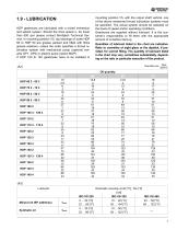
1.9-LUBRICATION HDP gearboxes are lubricated with a mixed immersion and splash system. Should the drive speed n be lower than 500 rpm please contact Bonfiglioli Technical Service. In mounting position V5, top bearings of sizes HDP 60 to HDP 90 are grease packed and fitted with Nilos grease retainers, unless the order specifies a forced lubrication system with mechanical pump (optional variants OP1, OP2) or electric pump (option MOP). If HDP 100 to 140 gearboxes have to be installed in mounting position V5, with the output shaft vertical, one of the above mentioned forced lubrication systems must be...
Open the catalog to page 9
Lubricant must be pre-heated through the appropriate electric resistance (HE option) in the following cases: • operation at ambient temperatures lower than 0 °C / 32 °F. • operation of gear units lubricated by oil immersion and splashing when the minimum ambient temperature exceeds the pour point of lubricant by less than 10 °C / 50 °F. • Upon starting up gear units with forced lubrication systems (options OP1, OP2 or MOP) if the oil viscosity exceeds 1800 cst. Depending on the type of lubricant used, this value may be produced with ambient temperatures between 10 °C / 50 °F and 20 °C / 68 °F...
Open the catalog to page 10
2.2.4 - CALCULATING THE RESULTING OVERHUNG LOAD External transmissions keyed onto input and/or output shafts generate loads that act radially onto same shaft. Resulting shaft loading must be compatible with both the bearing and the shaft capacity. Namely shaft loading (Rc1 for input shaft, Rc2 for output shaft), must be equal or lower than admissible overhung load capacity for shaft under study (Rx1 for input shaft, Rx2 for output shaft). OHL capability listed in the rating chart section. The procedure described above applies to both the input shaft and the output shaft, but care must be taken...
Open the catalog to page 11
BONFIGLIOLI RIDUTTORI
Open the catalog to page 12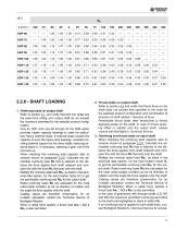
1. Overhung loads on output shaft Refer to section 4J_, and verify that both the radial and the axial force acting onto output shaft do not exceed the maximum permitted for the selected product configuration. Only for HDP units size 60 through 90 the HDB option provides higher capacity bearings to cater for particularly heavy external loads. If external loads exceed the capacity of even the heavy-duty bearings, consider providing external support for the drive shafts, reducing external loads or, if necessary, selecting a gear unit of the next size up. When checking the overhung load capacity...
Open the catalog to page 13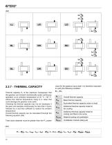
BONFIGLIOLI RIDUTTORI 2.2.7 - THERMAL CAPACITY Thermal capacity PT is the maximum horsepower that the gearbox can transmit mechanically under continuous operation at an ambient temperature of 20 °C / 68 °F, without the internal temperature rising to a value that could damage the gearbox inner parts. Checking the thermal capacity may not be necessary if the gear unit operates continuously for less than 3 hours followed by a rest time sufficient to restore the ambient temperature. Overall thermal capacity can be calculated throuhgh the following equation (A9). Total value obtained must be greater...
Open the catalog to page 14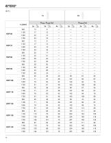
BONFIGLIOLI RIDUTTORI
Open the catalog to page 16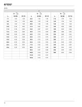
BONFIGLIOLI RIDUTTORI
Open the catalog to page 18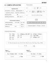
2.3 - SAMPLE APPLICATIONApplication data a) _ 1100 n2 90 drive speed n1 = 1100 rpm Safety factor S.F. = 2 b) o/p speed n2 = 90 rpm Torque Tr2 = 25,000 lbs-in Operating cycle per hour: 100% ^ f|NT = 1 Pt = (PtB X fTA X fAMB X fALT X f|NT) — (PtO X fi X frh) + (PfAN X frA X fALT) + PsR + PmRCW + PmCRA= 25 hp Option 1 Option 2 - Fan cooling - Cooling coil
Open the catalog to page 19All Bonfiglioli catalogs and technical brochures
 Product Range Wind Solutions
28 Pages
 Solutions for Packaging
16 Pages
 Solution Condtruction Industry
52 Pages
 Product Range Mobile Solution
44 Pages
 Marine and Offshore
20 Pages
 Worm Gear Series
86 Pages
 V series Motovariator
362 Pages
 Mobile Solutions Product Range
44 Pages
 Wind Solutions
24 Pages
 Mechatronic Life Cycle
4 Pages
 Bonfiglioli Digital Tools
12 Pages
 Wind Solutions Product Range
28 Pages
 Solutions for Water Treatment
16 Pages
 Solutions for Food & Beverage
20 Pages
 Spare parts list W Series
24 Pages
 Drives for Road Machinery
36 Pages
 Drives for Excavators
24 Pages
 Solutions for access platforms
16 Pages
 Solutions for Mining
20 Pages
 Solutions for Intralogistics
8 Pages
 VF-W series - Wormgears IE2-IE3
298 Pages
 VF-W series - Wormgears - Atex
46 Pages
 VF-W series - Wormgears
268 Pages
 Modular planetary gearboxes
560 Pages
 600W2/3 Series
2 Pages
 610X Series
2 Pages
 Wheel drives - 600 Series
2 Pages
 600Y3 Series
2 Pages
 Widest Range of Final Drive
2 Pages
 600W series
2 Pages
 Active Cube 7
2 Pages
 Power Drive VCB400
16 Pages
 Advanced Standard Drive - Agile
52 Pages
 Solution Drive - Active Series
72 Pages
 BC - DC electric motors
20 Pages
 3/H Combined gearboxes
20 Pages
 RAN series - Mitre gears
28 Pages


- Synchronous motor
- Alternating current motor
- Multipole motor
- Electric gearmotor
- Asynchronous motor
- Planetary gearbox
- Coaxial gearhead
- Electromotor for industrial applications
- Three-phase motor
- Precision gearhead
- Servo-motor
- Right angle gearhead
- Direct current gear-motor
- Compact gearhead
- 4-pole motor
- Solid-shaft gearhead
- Compact electromotor
- IP55 motor
- Hollow-shaft gearhead