Overview: This document is a technical catalog from Bondioli & Pavesi SpA, focusing on SFT drivelines and accessories. It emphasizes safety, functionality, and technological advancements in driveline design.
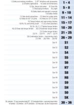
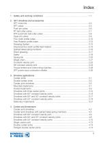
1. Safety and Working Conditions: The primary focus is on operator safety, with SFT driveshafts designed to exceed international safety standards. The catalog stresses the importance of a cautious operator and robust equipment.
2. SFT Drivelines and Accessories: This section introduces the SFT range, highlighting the latest technical innovations and features designed for ease of use, reliability, and robustness in various applications.
3. Driveline Applications: Provides guidance on selecting appropriate driveline components based on specific applications, ensuring optimal performance and safety.
4. Codes and Dimensions: Details the structure of driveline codes and dimensions, offering a comprehensive range of available options.
5. Size, Torque, and Power: Discusses maximum torque, dynamic torque, and the theoretical life of cardan joints, including factors like velocity, angle, and lubrication coefficients.
6. Cross Kits: Information on cross kits for single and constant velocity joints, emphasizing durability and performance.
7. Telescoping Members: Describes the characteristics and types of telescoping members, including four-tooth and free rotation profile tubes.
8. Driveline Lengths: Covers definitions, applications, and critical speeds related to driveline lengths, ensuring compatibility and safety.
9. Safety Labels and Operator’s Manuals: Details the importance of safety labels and manuals, tailored to the country of destination.
10. Safety Shields: Provides technical data on safety shields, including optional outer cones and restraint chains.
11. Yoke-Shaft Connections: Discusses various yoke types and their applications, ensuring secure and efficient connections.
12. Yokes for Cardan Joints: Details different yoke designs for cardan joints, focusing on performance optimization.
13. Yokes for CV Joints: Information on yokes for 80° and 50° constant velocity joints, highlighting their specific applications.
14. Torque Limiters and Clutches: Explains the use of torque limiters and overrunning clutches, essential for protecting driveline components.
15. Lubrication: Emphasizes the importance of proper lubrication for maintaining driveline efficiency and longevity.
Conclusion: The catalog serves as a comprehensive guide for selecting and using driveline components safely and effectively, with a strong emphasis on innovation and safety.
Safety and Handling: The document emphasizes the importance of safety when handling drivelines. It advises against using shield restraint chains for storage and stresses keeping the driveline horizontal to prevent injury or damage. Proper safety equipment should be worn during maintenance, and only original spare parts should be used.
Drivelines and Accessories: Bondioli & Pavesi's SFT range of drivelines is designed to meet modern agricultural demands for safety, reliability, and low maintenance. The drivelines comply with international safety standards and are engineered for easy installation and long-lasting lubrication.
Cross Kits: These are specifically designed for agricultural applications, offering high strength and extended lubrication intervals. The design focuses on higher strength trunnions and increased needle bearing life.
Yokes: SFT yokes are optimized for universal joint performance, designed to minimize deflections and maintain accurate alignment, which is crucial for high performance and longevity.
Profile Tubes: The Four-Tooth profile tubes are designed for high strength and low thrust, allowing for extended lubrication intervals and reduced wear. Free Rotation tubes simplify driveline installation by allowing end yokes to rotate for easier alignment.
Greasing System: The document describes a greasing system that facilitates easy lubrication of profile tubes, extending the service life of the driveline components.
Specifications: The document outlines the specifications of various driveline components, including advanced four-tooth profile heat-treated telescoping members, splined telescoping members, and constant velocity (CV) joints. The advanced four-tooth profile provides maximum torque resistance and expanded contact surfaces, while splined telescoping members are designed for high torque applications with frequent sliding under load.
Procedures: Detailed procedures for lubrication and maintenance are provided. The Direct Greasing system allows for easy lubrication of splined telescoping members without disassembly. The document emphasizes the importance of regular lubrication to reduce wear and extend the life of joints and bearings.
Standards and Safety: The document references compliance with various standards, including CUNA, UNI EN ISO 5674, ANSI/ASABE AD5674, and the European Community’s Machinery Directive (2006/42/CE). Safety features include shield bearings designed to withstand compressive forces and safety shields that prevent rotation and protect users.
Recommendations: Recommendations include not shortening the driveshaft by more than 50 mm and ensuring proper overlap of profiles throughout the operating range. The document also advises on the use of the Single Chain system for restraining driveline shielding and highlights the benefits of the SFT EL CV joint, which requires less frequent lubrication.
Key Features: - Advanced four-tooth profile for maximum torque resistance. - Splined telescoping members with Direct Greasing system. - Safety shields designed to meet international safety standards. - Constant velocity joints with reduced maintenance requirements. - Permanently lubricated torque limiters and overrunning clutches for higher efficiency.
Specifications and Lubrication: The document discusses the lubrication and assembly of RL Overrunning Clutches and LR Torque Limiters, which are permanently lubricated with NLGI 2 grease and sealed, requiring no further lubrication throughout their service life.
SFT Shields: SFT shields are safety devices designed to integrate with driveline guards, accommodating drivelines with CV joints, torque limiters, or overrunning clutches. They conform to ANSI/ASABE S604.1 and UNI EN ISO 4254-1 standards, ensuring a minimum overlap of 50 mm with the driveline. Maintenance is simplified by detaching the outer guard.
Driveline Applications and Cardan Joints: The document explains the mechanics of cardan joints, which consist of two yokes connected by bearings. It highlights the variation in speed caused by joint angles and provides formulas to calculate driven yoke speed. The document also discusses the importance of limiting joint angles to prevent excessive vibration and stress, providing recommended maximum angles based on rotational speed.
Double Cardan Joints: Double cardan joints eliminate speed variations by using two joints with parallel inner yokes and equal joint angles. The document provides guidelines for calculating equivalent joint angles and stresses the importance of proper installation to accommodate movement between shafts.
Driveline Types and Installation: The document categorizes drivelines based on implement types (mounted, towed, stationary) and emphasizes the importance of selecting appropriate drivelines for specific applications. It discusses the connection methods, such as quick coupling for tractor PTOs, and the importance of maintaining proper driveline length to prevent bottoming out.
Maintenance and Safety: Proper lubrication of telescoping members is crucial to reduce wear and extend the life of cardan joints. The document introduces a Greasing System for easier maintenance. It also highlights the importance of correct attachment of retaining chains to prevent damage to driveline shielding, in compliance with safety standards.
Driveline Applications Overview: This document provides detailed guidelines on the use and maintenance of drivelines in towed implements, focusing on ensuring safety and efficiency during operation.
Towed Implements and Driveline Configuration: Towed implements are connected to tractors via a pin that allows for articulating movements, with the position standardized according to ISO 5673 and ANSI/ASABE AD5673 standards. It is crucial to use the drawbar hitch as intended by the manufacturer to avoid damage and hazards. The document emphasizes maintaining appropriate joint angles during operation and turning, recommending equal angle hitches to minimize speed variations.
Telescoping Members and Thrust Forces: The document discusses the importance of selecting the correct telescoping members to manage axial thrust forces generated during operation. It provides a table of thrust-to-torque ratios for different tube types, highlighting Rilsan® coated tubes for their minimal thrust generation. Proper lubrication is essential to reduce wear and extend the life of components.
Driveline Length and Safety Considerations: Guidelines are provided for selecting driveline length to prevent telescoping members from bottoming out during maximum turning angles. The document stresses the importance of maintaining the integrity of safety shields and correct attachment of retaining chains to prevent damage.
Driveline with Three Cardan Joints: For implements with long hitches, a driveline with three cardan joints may be used to prevent excessive joint angle differences. The document explains the configuration and phasing required to minimize speed variations.
80° Constant Velocity Joints: Drivelines with 80° constant velocity joints are recommended for implements with long drawbar hitches, as they accommodate wide joint angles without generating velocity variations. These joints require less frequent lubrication and are suitable for applications with frequent turning.
Installation and Maintenance: The document highlights the importance of quick and easy connection of the driveline to the tractor PTO, facilitated by quick coupling mechanisms. It also emphasizes the necessity of regular lubrication, simplified by optional greasing systems, to maintain driveline performance and safety.
Specifications and Recommendations: 1. 80° Constant Velocity (CV) Joints: Recommended for applications with frequent turning and where the normal working position does not exceed 25°. Not suitable for stationary or three-point hitch applications. 2. 50° Constant Velocity (CV) Joints: Used as secondary drivelines for complex implements. They transmit power without speed variations, reducing vibrations and stress.
Driveline Applications: 1. Length Selection: Ensure telescoping members do not close completely or "bottom out". Maintain adequate overlap while transmitting power. 2. Stationary Implements: Operate from a fixed position, ensuring small and equal joint angles to avoid vibrations and stress. 3. Safety and Maintenance: Use torque limiters to prevent damage from overloading. Ensure all rotating parts are guarded.
Codes and Dimensions: 1. Driveline Codes: A fifteen-position alphanumeric code specifies the driveline, including shaft type, dimensions, and yokes. 2. Yokes and Torque Limiters: Three-digit codes identify yokes or torque limiters, specifying the type of joint. 3. Guarding System: Integral guarding system with shields on the tractor and implement to ensure safety.
Key Data from Tables: 1. Driveline Sizes: Various sizes (S1, S2, S4, etc.) with specific dimensions and specifications. 2. Telescoping Members: Specifications for splined telescoping members and their dimensions.
Critical Information: 1. Safety: Correct use of drivelines and integrity of safety shields are essential for user safety. 2. Installation: Ensure proper attachment of restraint chains and avoid interference with other components. 3. Operational Limits: Do not exceed speed and power requirements as stated in the implement manual.
Specifications and Dimensions: The document outlines the specifications and dimensions for various SFT drivelines with constant velocity (CV) joints. It includes details on the dimensions of the H7 80° CV joint, which are similar to the S6 80° CV joint but differ in material specifications to allow for higher torques. The maximum permitted angle for the SH size CV joint is 75°.
Codes and Dimensions: For SFT drivelines with 80° and 50° CV joints, all rotating parts must be guarded. The document specifies the need for torque limiters or overrunning clutches on the implement end of the driveline. It provides codes for different driveline sizes and types, including telescoping members and minimum collapsed lengths of driveshafts. Warning labels and instruction manuals should be selected based on the country of use.
Safety and Guarding: All rotating parts must be guarded, and the document emphasizes the importance of an interactive guarding system formed by shields on the tractor and implement machine. Shield restraint chains and the Single Chain Restraint System are discussed, along with the specifications for tractor and implement end yokes.
Torque and Power: The document discusses the selection of driveline size based on functional requirements, torque, speed, joint angle, and lubrication frequency. It highlights the need for drivelines to handle varying torque levels, especially in agricultural applications. The document provides torque values for different driveline sizes and discusses the use of torque limiters to prevent overloads.
Torque Limiters: Different types of torque limiters are recommended based on the duty cycle of the implement. Ratchet, shear bolt, and automatic torque limiters are used for constant or alternating duty cycles with possible overloads. Friction torque limiters are suitable for alternating cycles with frequent overloads, while combination
friction clutch torque limiters are used for high inertial loads.
Specifications: The document outlines the specifications for cardan joints, focusing on maximum dynamic torque (Mdmax) which is crucial for ensuring the joint operates effectively under normal conditions. The torque values must be below Mdmax to ensure longevity.
Procedures: The lifetime of a cardan joint is calculated based on transmitted torque, rotational velocity, joint angle, and lubrication frequency. The document provides formulas to relate torque and power, and emphasizes the importance of these parameters in determining the joint's lifespan.
Norms and Standards: The document references ANSI/ASAE S331.5 for classifying drivelines based on dynamic and static strength, with categories for Regular Duty and Heavy Duty.
Recommendations: Proper lubrication is critical, with NLGI 2 grease recommended. Lubrication frequency affects the joint's lifetime, with a standard frequency of every 50 hours suggested. The document also advises on the use of torque limiters to prevent damage.
Key Data from Tables and Charts: - Torque values for different sizes (S1, S2, etc.) are provided in both Nm and in.lb. - Coefficients for velocity (Kn), angle (Kα), and lubrication (KL) are given to adjust lifetime calculations. - The document includes tables for dynamic torque ratings and nominal power and torque for different joint sizes.
Critical Information: - Maximum dynamic torque (Mdmax) is a critical parameter for joint longevity. - Proper lubrication and maintenance are essential to prevent joint failure. - The choice of driveline size should consider the maximum torque and the specific application requirements.
Best Practices: - Regular lubrication and use of appropriate grease. - Monitoring and adjusting for joint angle and rotational speed to optimize joint life. - Selecting the correct size and type of cardan joint based on application needs and torque requirements.
Specifications: The document details various types of telescoping members used in driveline systems, focusing on their design, materials, and capabilities. The Advanced Four-Tooth Profile is highlighted for its maximum torque resistance and extended contact surfaces, allowing for a long lifespan. SK telescoping members are constructed with a thick outer profile tube and a solid inner bar, capable of transmitting torque up to 11,000 Nm. The profile teeth are positioned at 95° and 85°, ensuring proper phasing of universal joints.
Procedures: The document outlines the process for achieving maximum extension by welding the outer tube to the yoke, eliminating the roll pin, and allowing the inner tube to extend further. This modification is available upon request and incurs an additional cost.
Norms and Recommendations: Free Rotation profile tubes are designed to allow up to 60° rotation between driveline ends, aiding in the alignment of splined yokes to the PTO. These tubes must be specified according to the power direction to ensure proper joint phasing. Rilsan® coating is recommended to reduce telescopic thrust, and an optional Greasing System is available for rapid lubrication.
Key Data and Tables: The document includes tables listing various telescoping member types, their dimensions, and torque capacities. It specifies the codes for ordering different tube lengths and configurations, including regular, maximum extension, and Rilsan® coated versions.
Critical Information: - Maximum torque capacity: 11,000 Nm for SK members. - Proper phasing is crucial for universal joint functionality. - Rilsan® coating and greasing systems are recommended for enhanced performance and longevity. - Custom extensions and coatings are available upon request, with associated costs.
Specifications: The document outlines specifications for Rilsan® coated tubes, indicating that adding '1500' or '1000' to the code of drilled roll pin tubes results in lengths of 1.5 meters or 1 meter, respectively. Various tube sizes and their corresponding codes are listed, along with maximum torque values (Mmax) for different configurations.
Telescoping Members: The document describes splined telescoping members, identified by the letter 'S' in the driveline code. Yokes and welded splined sleeves are provided for drivelines shorter than 610 mm, with longer lengths requiring a welded tube between the sleeve and yoke. Codes for ordering spare parts are provided, with examples illustrating the coding system.
Greasing System: Lubrication is emphasized as crucial for reducing wear and extending the life of joints and bearings. The Greasing System, indicated by the letter 'G' in the shaft code, facilitates lubrication of telescoping profile tubes while installed. Ordering details for the Greasing System as a spare part are provided.
Driveline Length: The document explains the importance of selecting appropriate driveline lengths to prevent telescoping members from closing completely or extending excessively. It provides guidelines for determining minimum and maximum lengths (Lw, Lt, Ls) based on application requirements and joint types. Tables list these values for various tube sizes and configurations.
Critical Speed: The document mentions critical speed considerations for drivelines, advising consultation with the engineering department for lengths or speeds exceeding specified limits.
Overview: The document discusses the dynamics and safety considerations of rotating drive shafts, particularly in agricultural machinery. It highlights the importance of understanding critical speed, safety labels, and the design of safety shields.
Critical Speed and Dynamics: Rotating shafts can become dynamically unstable at high speeds, leading to vibrations and potential mechanical failure. This instability occurs when the driveline's speed approaches its critical speed, which is the flexural resonance frequency. Factors affecting critical speed include shaft length, diameter, and material elasticity. To prevent failure, the operating speed should be below the critical speed. For long power transmission applications, multiple drivelines with intermediate supports are recommended.
Safety Labels and Manuals: Drivelines are equipped with safety labels and operator manuals to comply with international safety standards. These labels provide essential safety information and are tailored to the destination country’s language requirements. The operator's manual includes instructions for safe use and maintenance, and a QR code for accessing additional resources online.
Safety Shields: SFT shields are designed to meet international safety standards, providing protection through robust components. The shields are structured to minimize flexural stress and extend the lifespan of the driveline. They are equipped with grease fittings for easy maintenance and are designed to integrate with tractor master shields as per ISO and ANSI standards. Optional extended outer cones are available for additional protection, especially in applications involving processed materials.
Recommendations: Implement manufacturers should test drivelines under maximum expected conditions and clearly state speed and length limits in the operating manual. Safety shields should be properly installed and maintained to ensure operator safety.
Specifications: The document outlines the specifications for driveline shield cones and plates, including spare parts codes for optional extended cones and plates. It emphasizes that driveline shield cones can cover joints partially or completely but are not substitutes for proper implement input connection (IIC) shields, tractor master shields, or other appropriate guarding.
Procedures: The document details the installation and attachment procedures for safety shields, including the use of restraint chains to prevent shield rotation with the driveline. It provides recommendations for attaching shield restraint chains properly and adjusting their length to ensure free movement of the driveline.
Standards and Regulations: The document references several standards, including UNI EN ISO 5674, ANSI/ASABE AD5674, and EN 12965, which specify requirements for shield restraints and their ability to withstand certain loads. It also mentions the Machinery Directive (2006/42/CE) requirements for primary drivelines.
Recommendations: Recommendations include ensuring proper attachment of shield restraint chains, adjusting chain length to avoid excessive wrapping, and not using chains to support the driveline when not in use. It also suggests providing suitable fastening points for chains on implements.
Key Data from Tables: The document includes tables listing dimensions and codes for various shield components, such as shield cones and restraint chains. It specifies the use of S-hooks and Spring Link devices for different driveline sizes and provides codes for ordering complete shield kits.
Additional Features: The document describes optional features like the Single Chain system, which prevents shield damage due to incorrect chain connections, and the availability of shield kits with access for the Greasing System. It also outlines the configurations for different shield cones based on joint types and lengths.
Overview: The document provides detailed technical specifications and procedures for the installation and maintenance of yokes and drivelines used in agricultural machinery. It includes information on various types of yokes, their connections, and the recommended torque values for secure installation.
Specifications: The document outlines the specifications for different yoke types, including taper pin yokes, push pin yokes, ball collar yokes, and automatic ball collar yokes. Each type is described with its dimensions, compatible shaft sizes, and specific part codes for ordering replacements.
Procedures: Instructions are provided for connecting and disconnecting drivelines to the PTO (Power Take-Off) using automatic mechanisms that allow for hands-free operation. The document emphasizes ensuring the collar snaps back to its original position after connection.
Torque Values: Recommended torque values are specified for different yoke and shaft combinations to ensure secure connections. For example, 150 Nm for 1 3/8” Z6 and Z21, and 220 Nm for 1 3/4” Z6 and Z20.
Yoke Types and Applications: The document categorizes yokes based on their application, such as single cardan joints, and provides detailed tables with dimensions and part codes. It also highlights the importance of using the correct tapered pins and not substituting them with standard bolts.
Key Recommendations: Regular checks are recommended to ensure nuts are tightened to the specified torque before each use. The document advises against using certain yokes on tractor PTOs and provides specific part codes for ordering replacements.
Data Tables: Extensive tables provide detailed measurements and part codes for various yoke types, including dimensions like A, H, S, D, and B, along with spare part codes for easy reference and ordering.
Overview: This document provides detailed specifications and configurations for various types of yokes used in cardan and constant velocity (CV) joints. It includes dimensions, spare part codes, and specific applications for different yoke types.
1. Yokes for Single Cardan Joints:- Tube Yokes: Specifications for tube yokes designed for Advanced Four-Tooth profile tubes, both outer and inner, are provided. Key dimensions such as A, H, D1/D2, F, E, ØD, B, and R are listed along with spare part codes.
- Splined Bar Telescoping Members: Details on yokes for splined bar telescoping members, including dimensions and spare part codes, are outlined.
2. Yokes for Double Cardan Joints:- Central H-Yokes: Specifications for standard and flanged double joints are provided, including dimensions and spare part codes.
3. Yokes for 80° Constant Velocity Joints:- General Specifications: Includes centering ball features, welding details, and connection types. Dimensions and driveline codes for outer and inner yokes are specified.
- SH CV Joint: Designed for high-power applications, featuring two centering discs for enhanced torque handling. Maximum joint angle is 75°.
- Torque Limiters and Clutches: Optional integration with outer yokes, with installation guidelines and safety precautions.
4. Ball Collar Yokes:- Tractor and Implement Sides: Various collar types and configurations are detailed, with dimensions and spare part codes for both tractor and implement sides.
5. Taper Pin Yokes:- Counter-Clockwise Rotating Drivelines: Specifications include recommended tightening torques and spare part codes.
6. CV Housings:- Details on CV housings, including dimensions and spare part codes, are provided.
7. Tube Yokes for Four-Tooth and Free Rotation Profiles:- Specifications for tube yokes designed for outer and inner Four-Tooth and Free Rotation profile tubes, including dimensions and spare part codes.
Overview: This document provides detailed specifications and guidelines for yokes used in constant velocity (CV) joints, particularly focusing on 50° and 80° CV joints. It includes information on various types of yokes, torque limiters, and overrunning clutches used in agricultural implements.
Specifications: The document outlines the dimensions and codes for different yokes, including tube yokes for inner and outer profiles, ball collar yokes, and taper pin yokes. It specifies the use of these yokes in different configurations and their compatibility with various driveline components.
Procedures: Instructions are provided for the installation of torque limiters and overrunning clutches, emphasizing their role in protecting implements from overloads and ensuring efficient power transmission. The document advises on the correct placement of these components on the implement side of the driveline.
Standards and Recommendations: The document recommends specific torque settings for different types of torque limiters, considering factors such as median torque and maximum torque limits. It suggests using ratchet torque limiters for drivelines operating at lower speeds and friction clutch torque limiters for systems with frequent overloads.
Key Data: Tables in the document provide detailed measurements and part codes for various yoke configurations, including dimensions like diameter, length, and specific part codes for spare parts. Torque settings for different limiters are also detailed, with maximum suggested settings highlighted for specific operating conditions.
Critical Information: The document highlights the importance of selecting the appropriate torque limiter based on the implement's duty cycle and the type of loads it transmits. It also stresses the need for regular maintenance and lubrication of torque limiters to ensure optimal performance.
Overview: The document provides detailed technical specifications and guidelines for the installation and maintenance of torque limiters and shear bolt torque limiters used in drivelines. It emphasizes the importance of safety measures, such as guarding all rotating parts and ensuring proper installation of torque limiters on the implement side.
Specifications: The document lists various models of ratchet torque limiters (LC2, LC3, LC4, LT1, LT2, LT3, LT4) and shear bolt torque limiters (LB). Each model is associated with specific driveline codes and spare parts, including grease fittings, outer housing, ratchet and spring kits, hubs, locking plates, snap rings, and ball collar kits. The document provides technical data such as size, torque settings, and lubrication requirements.
Procedures: For primary drivelines, it is crucial to install any torque limiter or overrunning clutch on the implement side. The document advises on seasonal lubrication for ratchet torque limiters and provides specific lubrication intervals for shear bolt torque limiters. It also outlines the procedure for replacing shear bolts, emphasizing the need to use bolts of equal length, diameter, and grade as the original for safety and reliability.
Standards and Recommendations: The document specifies the use of metric class 8.8 steel bolts with a minimum strength of 800 N/mm² for shear bolt limiters. It also provides ISO and SAE standards for shear bolts, along with recommended tightening torques. The document highlights the importance of not exceeding the maximum torque settings for drivelines and provides guidelines for torque settings based on the type and size of telescoping members.
Key Data from Tables: The tables in the document provide detailed information on torque settings, spare part codes, and technical specifications for each model of torque limiter. They also include recommended settings for different sizes and types of drivelines, as well as the maximum recommended settings for specific profiles.
Critical Information: The document stresses the importance of guarding all rotating parts and ensuring accurate torque settings to prevent damage to drivelines. It also highlights the need for regular maintenance and proper replacement of shear bolts to ensure the safety and functionality of the equipment.
Overview: This document provides detailed specifications and guidelines for the LR24 and LR35 series components, focusing on their use in mechanical systems operating at different speeds (540 min-1 and 1000 min-1). It includes information on outer housings, bushings, spring kits, cams, hubs, and various other components essential for the assembly and maintenance of these systems.
Specifications: The document lists various components such as outer housings, bushings, spring kits, sleeves, cams, taper pins, hubs, sealing rings, O-rings, locking plates, and snap rings. Each component is specified for use at either 540 min-1 or 1000 min-1, indicating their suitability for different operational speeds.
Procedures and Recommendations: For primary drivelines, it is recommended to install torque limiters or overrunning clutches on the implement side. All rotating parts must be guarded to ensure safety. The document also provides recommended settings for torque limiters at different operational speeds.
Friction Torque Limiters: The document explains the function of friction torque limiters, which are used to limit torque during overloads. It describes the operation of friction clutches, their effectiveness in limiting overloads, and the importance of selecting appropriate settings based on application conditions. The document distinguishes between adjustable (FV, FFV) and non-adjustable (FT, FK) torque limiters.
Technical Data and Settings: Detailed tables provide technical data, including torque settings, spring codes, and compression measurements for various models of friction clutches. The document emphasizes the importance of not altering defined settings to avoid excessive wear and potential damage.
Release System: The document describes a release system that reduces pressure on friction linings during storage, preventing adhesion and seizure. It includes instructions for adjusting the system using hex screws and provides guidelines for verifying proper operation after storage.
Safety Warnings: Friction clutches may become hot during operation, and users are advised not to touch them. The area around the friction clutch should be kept clear of flammable materials, and prolonged slipping should be avoided to prevent excess heat and wear.
Overview: The document provides detailed technical specifications and guidelines for the installation and maintenance of friction torque limiters, specifically the FFV and FT series. These components are crucial for managing torque in primary drivelines, ensuring safety and efficiency in mechanical operations.
Specifications: The document outlines various models of friction torque limiters, including FFV32, FFV42, FFV34, FFV44, FT22, FT32, FT42, FT34, and FT44. Each model is described with specific dimensions, settings, and spare part codes. The torque limiters are adjustable, with settings provided for different operational velocities, particularly at 1000 min-1.
Installation Guidelines: It is emphasized that torque limiters or overrunning clutches should always be installed on the implement side of primary drivelines. All rotating parts must be adequately guarded to ensure safety during operation.
Technical Data: The document includes tables listing spare parts, their descriptions, and technical codes. Key components such as bolts, coil springs, flange yokes, bushings, friction linings, and pressure plates are detailed with their respective sizes and technical specifications.
Adjustable Settings: The FFV series torque limiters are adjustable, with specific settings for different models and operational conditions. The document provides maximum recommended settings for safe operation at specified velocities.
Non-Adjustable Settings: The FT series friction clutches are non-adjustable, with torque determined by the thickness of the Belleville spring. These clutches are designed to maintain constant pressure and self-compensate for friction lining wear.
Safety Recommendations: The document advises against over-tightening bolts to prevent damage to the friction clutches. It also warns about the potential heat generation during use and recommends keeping the area around the friction clutch clear of flammable materials.
Conclusion: The document serves as a comprehensive guide for the selection, installation, and maintenance of friction torque limiters in mechanical systems, emphasizing safety and operational efficiency.
Overview: This document provides detailed specifications and settings for various friction torque limiters (FT) used in driveline systems. The document includes technical data, spare part codes, and installation guidelines for different models such as FT32, FT42, FT34, and FT44.
Specifications: Each friction torque limiter model is described with its non-adjustable settings, maximum recommended settings for specific velocities, and the joint angle (α) at which the clutch contacts the shield. The document specifies the torque capacities in Nm for different models and configurations.
Procedures: The document emphasizes the importance of installing torque limiters or overrunning clutches on the implement side of primary drivelines. It also stresses that all rotating parts must be guarded to ensure safety.
Spare Parts and Codes: Detailed lists of spare parts are provided for each model, including bolts, flange yokes, bushings, friction linings, and other components. Each part is associated with a technical code for easy identification and ordering.
Recommendations: The document recommends adhering to the maximum settings for specific velocities to ensure optimal performance and safety. It also highlights the necessity of guarding all rotating parts to prevent accidents.
Key Data: The document includes tables with technical data such as dimensions (B, F, G, α), torque capacities, and part codes. These tables are crucial for selecting the appropriate components and settings for specific applications.
Overview: The document provides technical specifications and guidelines for the installation and use of non-adjustable friction torque limiters, specifically the FT44R and FK series. These components are crucial for managing torque in primary drivelines, ensuring safety and efficiency in machinery operations.
Installation Guidelines: It is emphasized that torque limiters or overrunning clutches should always be installed on the implement side of primary drivelines. Additionally, all rotating parts must be properly guarded to ensure safety.
Specifications: The document details various components such as bolts, flange yokes, bushings, friction linings, and Belleville springs. It provides technical codes and data for each part, ensuring precise identification and replacement.
Friction Torque Limiters (FK Series): The FK series includes non-adjustable friction clutches equipped with Belleville springs, which maintain constant pressure and self-compensate for wear. The torque setting is determined by the spring thickness, and the clutches are available in five models with varying diameters and friction linings. The document lists standard and maximum recommended settings for each model, particularly for use at 1000 min-1.
Safety and Maintenance: Users are advised not to alter the settings to avoid excessive wear. Friction clutches can become hot during use, so it is important to keep the area clear of flammable materials and avoid prolonged slipping. Recommended tightening torques are specified for different models to ensure proper spring compression.
Combination Friction Torque Limiters and Overrunning Clutches: These are used in implements with high inertia, such as mower conditioners and square balers. They help manage torque during overloads and eliminate inverse torques during sudden deceleration. Three versions are available, with adjustable and non-adjustable options, and two different diameters.
Specifications: The document discusses various models of friction clutches and torque limiters, specifically FNV and FFNV models. FNV clutches use Belleville springs, while FFNV clutches use coil springs. Both models are available in two diameters: 180 mm and 202 mm, with four plates each. The FFNV clutches are not EU marked due to incomplete shielding as per Machinery Directive 2006/42/CE.
Procedures: The document outlines the importance of adjusting the torque settings of friction clutches to compensate for wear and maintain desired performance. It provides guidance on adjusting the compression of springs and the rotation of bolts to achieve the correct settings. Regular lubrication of overrunning clutches every 50 hours and after storage is recommended.
Standards and Recommendations: The document emphasizes the need for proper shielding of drivelines, especially for FFNV clutches, to comply with standards like UNI EN ISO 4254-1 and ANSI/ASABE S604.1. It also advises against altering the defined settings to prevent excessive wear on implements, drivelines, or tractors.
Key Parameters and Limitations: The reliable function of friction clutches depends on parameters such as temperature, pressure, and slipping velocity. The document provides maximum recommended torque settings for different models at a speed of 1000 min-1. It warns against prolonged slipping to avoid generating excess heat and wear.
Safety Precautions: Users are cautioned not to touch friction clutches during use due to heat generation. The area around the clutch should be kept clear of flammable materials. All rotating parts must be guarded, and users should not approach the implement until all parts have stopped completely.
Specifications and Components: The document outlines various components and specifications for friction torque limiters, shield cones, greasing systems, and drivelines. It includes detailed codes and measurements for different parts such as yokes, cardan joints, and overrunning clutches. The document specifies the maximum recommended speed for certain components as 1000 min-1 and provides torque values for different configurations.
Procedures and Safety Recommendations: Key safety procedures include ensuring all rotating parts are guarded, securely attaching drivelines at both ends, and verifying that all connections are tight. It warns against touching friction clutches during use due to heat and advises keeping the area clear of flammable materials. The document emphasizes the importance of proper installation of torque limiters on the implement side of primary shafts.
Lubrication and Maintenance: The document highlights the importance of regular lubrication, specifying a frequency of 50 hours for standard conditions, with potential extensions to 250 hours under certain conditions. It provides a nomogram for calculating the lifetime of cardan joints based on torque, speed, and joint angle, and discusses how lubrication frequency can be adjusted based on these factors.
Optional Features and Customization: Optional features include extended shield cones for different lengths and diameters, and a greasing system for easy lubrication of telescoping members. The document provides codes for ordering these optional features and explains how to modify driveline codes to include them.
Technical Data and Calculations: Technical data includes torque and power values for different joint sizes, conversion ratios for power and torque, and detailed measurements for telescoping members. The document provides tables with maximum working lengths and temporary lengths for drivelines, and specifies the maximum transmitted torque for various configurations.
Specifications: The document provides detailed specifications for various torque limiters and clutches, including ratchet torque limiters, shear bolt torque limiters, automatic torque limiters, and friction torque limiters. Each type is associated with specific codes, spare parts, and recommended settings. The maximum recommended speed for most components is 700 min-1, with some exceptions for 1000 min-1.
Procedures: Installation guidelines emphasize the importance of securing the driveline at both ends, ensuring all rotating parts are guarded, and verifying that all connections are tight. Specific instructions are provided for installing torque limiters and overrunning clutches on the implement side of primary shafts.
Standards and Recommendations: The document stresses the need for proper guarding of all rotating parts and adherence to safety standards. It also highlights the importance of regular lubrication, with a standard frequency of 50 hours, which may be extended under certain conditions.
Lubrication and Maintenance: Lubrication is critical for the longevity of cardan joint drivelines. The document provides a nomogram for calculating the theoretical life of a joint based on torque, speed, and angle, and offers guidance on adjusting lubrication frequency based on operational conditions.
Safety and Best Practices: Safety labels and operator manuals are essential for ensuring safe operation. The document advises on the use of restraint chains and proper shielding to prevent accidents. It also warns against touching friction clutches during use due to heat generation.
Optional Features: Optional shield cones and greasing systems are available to enhance safety and maintenance. The document provides codes for ordering these features and explains their benefits.
Technical Data: The document includes tables with technical data for various components, such as torque settings, spare part codes, and recommended speeds. It also provides conversion ratios for power and torque calculations.
Specifications and Safety Guidelines: - Ensure all rotating parts are guarded to prevent accidents. - Drivelines must be securely attached at both ends before operation. - Torque limiters or overrunning clutches should be installed on the implement side of primary shafts. - Friction clutches can become hot; avoid contact and ensure the area is clear of flammable materials. - Drivelines with FFNV clutches are not EU marked due to incomplete shielding.
Recommended Settings: - Maximum recommended setting for 1000 min-1 is specified for various configurations. - Specific part codes and configurations are provided for different torque and speed settings.
Optional Features: - Shield cones are available in various lengths and diameters for both tractor and implement ends. - A Greasing System is available for easy lubrication of telescoping members, indicated by adding 'G' to the driveline code.
Driveline Components: - Standard SFT cardan joint drivelines require integrated guarding systems. - Telescoping members and driveline lengths are detailed in specific chapters. - Safety labels and operator manuals are essential for safe operation.
Technical Data and Calculations: - Nomogram provided for calculating single cardan joint lifetime based on torque, speed, and angle. - Lubrication frequency is crucial for longevity, with a standard interval of 50 hours, extendable under certain conditions. - Conversion ratios for power and torque are provided for different units.
Yokes and Attachments: - Various yoke configurations are detailed, including ball collar and push-pin yokes. - Recommended tightening torques are specified for different profiles.
Additional Notes: - Ensure all connections are secure, and all safety measures are in place before operation. - Consult specific chapters for detailed information on telescoping members, lubrication, and safety protocols.
Overview: This document provides technical specifications and guidelines for various driveline components, including yokes, torque limiters, and clutches. It emphasizes safety measures and installation procedures to ensure proper operation and maintenance.
Specifications: The document lists detailed specifications for different components such as ball collar yokes, overrunning clutches, torsionally resilient joints, shear bolt torque limiters, automatic torque limiters, friction torque limiters, and shield cones. Each component is described with measurements, codes, and recommended torque settings.
Procedures: Key procedures include ensuring secure attachment of the driveline at both ends, verifying the position of ball collars or push-pins, and checking the tightness of taper pins, bolts, or setscrews. It is crucial to guard all rotating parts to prevent accidents.
Safety Recommendations: The document stresses the importance of guarding all rotating parts and installing torque limiters or overrunning clutches on the implement side of primary shafts. It also warns against touching friction clutches during use due to heat generation and advises keeping the area clear of flammable materials.
Standards and Compliance: Some driveline components, such as those with FFV clutches, are not EU marked due to non-compliance with Machinery Directive 2006/42/CE. The document highlights the need for integrated guarding systems with the driveline guard.
Additional Features: The document mentions optional features like the Greasing System for easy lubrication and extended shield cones for additional protection. It provides instructions on how to incorporate these features into the driveline setup.
Specifications and Components: The document outlines various components and specifications for drivelines, including yokes, torque limiters, and overrunning clutches. It specifies the types of joints such as cardan joints, constant velocity joints (80° and 50°), and splined stub shafts. The document also details the associated shields and attachments for both the power take-off (PTO) and implement ends of the driveline.
Torque and Power Calculations: Nominal torque (Mn) and power (Pn) are calculated based on joint lifetime, speed, and lubrication frequency. The document provides formulas to convert power into torque and vice versa, using specific ratios for different units.
Lubrication and Maintenance: Lubrication frequency is critical for the longevity of cardan joint drivelines. The standard lubrication interval is 50 hours, but this can be extended to 250 hours under certain conditions. The document includes a nomogram for calculating the theoretical life of a single cardan joint based on torque, speed, and joint angle.
Telescoping Members and Length Specifications: Details are provided for standard and maximum extension tube codes, including four-tooth profile tubes with various coatings. Length specifications for maximum working, temporary, and non-rotational lengths are given, with a note to contact engineering for requirements beyond specified limits.
Safety and Installation Guidelines: Emphasizes the importance of secure attachment of drivelines at both ends before operation. It advises checking that all components, such as ball collars, push-pins, taper pins, bolts, and setscrews, are secure and tight. All rotating parts must be guarded.
Yokes and Clutches: Specifications for various yokes, including RT ball collar yokes and push-pin yokes, are provided. The document also covers overrunning clutches and torsionally resilient joints, with recommended torque settings and installation guidelines.
Torque Limiters: Details on shear bolt torque limiters and automatic torque limiters are included, with specific settings for different speeds. The document specifies that torque limiters or overrunning clutches should be installed on the implement side for primary shafts.
Additional Components: Information on restraint chains, safety labels, and operator manuals is provided, with specific codes for different countries and regions.
Specifications and Standards: The document outlines the requirements for machinery components, specifically focusing on friction clutches and torque limiters. It highlights the necessity for all rotating parts to be guarded and mentions that drivelines with FFV clutches are not EU marked due to non-compliance with Machinery Directive 2006/42/CE.
Procedures and Safety Recommendations: Friction clutches can become hot during use, and it is advised not to touch them. The area around the friction clutch should be kept clear of flammable materials, and prolonged slipping should be avoided to prevent excess heat and wear. For primary shafts, torque limiters or overrunning clutches should be installed on the implement side. It is crucial to ensure that the driveline is securely attached at both ends before operation, and all connections should be checked for security.
Product Codes and Settings: The document provides detailed product codes for various driveline components, including friction torque limiters and overrunning clutches, both adjustable and non-adjustable. It specifies the maximum recommended settings for these components at 1000 min-1.
Optional Features and Accessories: Optional shield cones are available for additional safety, with specifications for different lengths and diameters. A greasing system is also mentioned, which facilitates easy lubrication of telescoping members.
Installation and Maintenance: Instructions are provided for the installation of torque limiters and the importance of maintaining secure connections. The document emphasizes the need for integrated guarding systems and provides references to additional chapters for further details on telescoping members, driveline lengths, safety labels, and operator manuals.
Overview: This document provides detailed specifications and guidelines for the selection and maintenance of various types of joints and components used in drivelines, including cardan joints, constant velocity joints, and splined stub shafts. It also covers the associated shields, attachments, and optional components like torque limiters and overrunning clutches.
Specifications: The document outlines the types of joints available (cardan joint, 80° CV, 50° CV, or splined stub shaft) and their associated components. It specifies the three-digit code system used to identify yokes or clutches and the optional shield cones or greasing systems. The document also provides torque and power ratings for different joint sizes and configurations.
Procedures: Instructions are provided for calculating the lifetime of a single cardan joint using a nomogram, considering factors like torque, speed, and joint angle. The document emphasizes the importance of proper lubrication frequency to ensure the longevity of the driveline components.
Lubrication and Maintenance: The recommended lubrication frequency for SFT cardan joints is every 50 hours, with adjustments for heavy-duty applications. The document explains how to extend lubrication intervals based on theoretical and required lifetimes, as well as transmitted torque.
Component Details: Detailed specifications for telescoping members, restraint chains, yokes, and overrunning clutches are provided. The document includes maximum torque ratings, thrust-to-torque ratios, and recommended tightening torques for various components.
Safety and Installation: Safety precautions are highlighted, including ensuring secure attachment of drivelines, checking all connections, and guarding rotating parts. Specific instructions are given for the installation of torque limiters and overrunning clutches on the implement side of primary shafts.
Additional Information: The document includes tables with dimensions and codes for various components, as well as guidelines for selecting the appropriate yokes and clutches based on application requirements.
Specifications: - Maximum recommended torque is 10,000 Nm. - RL permanent lubrication with 8 plates. - Shear bolt torque limiter is used. - All rotating parts must be guarded, with integrated guarding systems on both tractor and implement sides. - Codes for size SK drivelines are provided for various components.
Procedures: - Torque limiters or overrunning clutches should be installed on the implement side for primary shafts. - Proper lubrication is essential for the longevity and reliability of cardan joint drivelines. - Lubrication frequency is generally every 50 hours, but can extend to 250 hours for specific applications. - Grease should be applied until it purges from all bearing caps, avoiding high pressures.
Standards and Recommendations: - Implement input connection shields must comply with international safety standards and integrate with driveline guards. - The Machinery Directive (2006/42/CE) and standards UNI EN ISO 4254-1 and ANSI/ASAE 318.15 require specific shielding measures. - Safety labels and instructions must be provided by implement manufacturers, emphasizing the importance of keeping shields in place.
Lubrication Details: - NLGI #2 grease is recommended for all crosses, telescoping members, and shields. - SFT drivelines can be equipped with a Greasing System for easier maintenance. - Direct greasing systems are available for splined telescoping members and advanced four-tooth profiles.
Safety and Maintenance: - All rotating parts must be guarded to prevent serious injury or death. - Shields should not be used as steps and must be functional and in place before operation. - Damaged or missing shields must be replaced with original spare parts.
Units of Measurement: Length: The international unit of length is the metre (m). Conversions include: 1 millimetre (mm) = 0.001 m, 1 centimetre (cm) = 0.01 m, 1 inch (in) = 0.0254 m = 25.4 mm, 1 foot (ft) = 0.3048 m = 304.8 mm, 1 yard (yd) = 0.9144 m. Area: The international unit of area is the square metre (m²). Conversions include: 1 square millimetre (mm²) = 0.000001 m², 1 square centimetre (cm²) = 0.0001 m², 1 hectare = 10,000 m², 1 acre = 4046.856 m². Angle: The international unit of angle is the radian (rad). Conversions include: 1 degree (°) = 0.017453 rad, 1 rad = 57.296°. Force: The international unit of force is the newton (N). Conversions include: 1 kilogram-force (kp) = 9.81 N, 1 gram (g) = 0.001 kp, 1 quintal (q) = 100 kp, 1 ounce (oz) = 0.2780 N = 0.02835 kp, 1 pound (lb) = 4.4482 N = 0.45359 kp. Pressure: The international unit of pressure is the pascal (Pa or N/m²). Conversions include: 1 atmosphere (atm) = 101325 Pa, 1 bar = 100,000 Pa, 1 kilogram per square millimetre (kp/mm²) = 9.8066 N/mm², 1 Torr = 133.322 Pa. Torque: The international unit of torque is the newton-metre (N·m). Conversions include: 1 inch-pound (in·lb) = 0.1129 N·m, 1 foot-pound (ft·lb) = 1.3563 N·m, 1 kilogram-metre (kp·m) = 9.8066 N·m. Speed: The international unit of speed is the metre per second (m/s). Conversions include: 1 kilometre per hour (km/h) = 3.6 m/s, 1 foot per minute (fpm) = 0.00508 m/s. Rotation or Angle Speed: The international unit of rotation speed is the radian per second (rad/s). Conversions include: 1 revolution per minute (rpm or min⁻¹) = 2π/60 rad/s. Power: The international unit of power is the watt (W). Conversions include: 1 kilowatt (kW) = 1000 W, 1 cavalli-vapore (CV) = 0.7355 kW, 1 horsepower (HP) = 0.7457 kW.




 1000 SERIES
 S2003 series
 S2001 series
 SFT series
 Aluminium Heat Exchanger | A86
 Aluminium Heat Exchanger | A26
 Aluminium Heat Exchanger | A31
 Aluminium Heat Exchanger | A35
 Aluminium Heat Exchanger | A46
 Aluminium Heat Exchanger | A48
 Aluminium Heat Exchanger | A50
 Aluminium Heat Exchanger | A56
 Aluminium Heat Exchanger | A60
 Aluminium Heat Exchanger | A65
 Aluminium Heat Exchanger | A70
 Aluminium Heat Exchanger | A75
 Aluminium Heat Exchanger | A80
 Aluminium Heat Exchanger | A83
 Electronic Joystick - HPEJ
 Grips - HPCI
 Fan Drive Systems
 Electronic Control Unit
 Multiple Pumps
 Silent Gear Pumps
 Standard Gearboxes - 2000 series
 Standard Gearboxes - 4000 series
 Standard Gearboxes - 3000 series
 Standard Gearboxes - 2001 series
 Standard Gearboxes - 1000 series
 Global 017 Catalog
 DC013
DC013







 SC013
SC013 GL013
GL013 AM013
AM013 BA013
BA013 GM013
GM013 OP013
OP013 QH012
QH012 SM013
SM013 Group presentation
 BIMA013
 S012 - BIMA
 S012 parte1
 S012
S012 Gearboxes / Paralle
 Fan Drive Systems
 Input implement connection shields
 PTO Driveshaft