
- Catalogs
- BONDIOLI & PAVESI
- Global 017 Catalog

Global 017 Catalog

Global 017 Catalog
The document details various types of telescoping tubes used in driveline systems, including triangle profile tubes, Rilsan®-coated tubes, heat-treated tubes, and splined telescoping members. Each type is identified by specific codes and dimensions, with options for different lengths and drilled configurations for roll pins.
Procedures:
Instructions are provided for selecting and ordering tubes based on their profiles and coatings. The document specifies how to add certain letters or numbers to the shaft code to select the desired tube type and length.
Standards and Safety:
Safety labels and operator manuals are included with the drivelines, adhering to international safety standards. The labels provide essential safety information and are tailored to the destination country’s language requirements. The document also outlines the safety features of the driveline shields, which are designed to be both functional and reliable.
Recommendations:
The document advises on the proper selection of driveline lengths and configurations to ensure compatibility with specific agricultural implements. It also emphasizes the importance of adhering to safety guidelines and using the correct labels and manuals for different regions.
Key Data from Tables:
The tables provide detailed measurements and codes for various tube types and configurations, including maximum working lengths (Lw), temporary lengths (Lt), and non-rotating shaft lengths (Ls). These measurements are crucial for ensuring the correct application and safety of the driveline systems.
Critical Information:
- The document highlights the importance of using the correct shaft codes and lengths for specific applications.
- Safety labels must be understood in the language of the destination country.
- Driveline lengths and configurations should be selected based on the specific requirements of the agricultural implement and operating conditions.
The document outlines the specifications for safety shields used in 80° constant velocity (CV) joints in global drivelines. These shields are designed to meet international safety standards such as ISO 500, 86/297/CEE, and ANSI/ASABE AD500. The shields are integrated with the tractor's master shield and include components like shield bearings, metal rings, and restraint chains.
Procedures:
1. Shield Installation: The shield is connected to the base cone and standard shield bearing, with an additional bearing on the CV joint's center housing.
2. Restraint Chains: Chains are used to prevent the shield from rotating with the driveline, as per UNI EN 12965 regulations. Proper attachment points must be provided by implement manufacturers.
Standards and Regulations:
1. Restraint Standards: UNI EN ISO 5674 and ANSI/ASABE AD5674 require restraints to withstand a load of 400 N and detach at loads under 800 N.
2. Machinery Directive: Section 3.4.7 of Annex 1 to the Machinery Directive (2006/42/CE) specifies design requirements for primary drivelines.
Recommendations:
1. Attach the shield restraint chain perpendicular to the driveline.
2. Adjust chain length to allow free movement of the driveline.
3. Avoid using chains to support the driveline when not in use.
Optional Features:
1. Spring Link Device: An optional feature that allows easy detachment and reattachment of the chain.
2. Extended Cones: Available in various lengths and diameters, these cones provide additional coverage but do not replace proper guarding.
Ordering Information:
Shield kits can be ordered with specific configurations, including optional Spring Link chains. The document provides codes for specifying shield types and configurations.
Critical Information:
1. Proper attachment and adjustment of restraint chains are crucial to prevent damage and ensure safety.
2. Extended cones and shield kits must comply with relevant standards and regulations.
3. Driveline shields are not a substitute for proper implement input connection shields or tractor master shields.
- Taper Pin Yokes: Designed for counter-clockwise rotation, not suitable for tractor PTO. Recommended tightening torque is 150 Nm for 1 3/8” Z6 – Z21 and 220 Nm for 1 3/4” Z6 – Z20.
- Round Bore Yokes: Includes specifications for interfering bolt yokes and round bore yokes da cutter, with detailed measurements for each type.
- Flange Yokes: Specifications include dimensions and spare part codes for various sizes.
- Yokes for Outer and Inner Tubes: Same type of yoke is used for regular, Rilsan®-coated, and heat-treated tubes.
- Ball Collar Yokes: Specifications for both tractor and implement sides, including automatic versions.
- Taper Pin Yokes: Designed for counter-clockwise rotating drivelines.
- Central Housing: Specifications for different sizes and configurations.
- Purpose: Protects implements from overloads and torque peaks, ensuring longevity and reliability.
- Types: Includes ratchet torque limiters, shear bolt limiters, automatic torque limiters, and friction torque limiters.
- Settings: Recommended settings for different types of limiters, considering median torque and maximum torque limits.
- Applications: Suitable for implements with high inertia and varying torque cycles.
- Detailed charts provide maximum torque settings (Mmax) for various components and configurations, with specific recommendations for use at 1000 min-1.
These devices are used to manage torque peaks and ensure smooth operation of machinery with heavy rotating masses. They are available in adjustable and non-adjustable versions, each with an overrunning clutch to transmit rotary motion in one direction only, typically counter-clockwise.
Overrunning clutches are designed to handle the inertia of implements during deceleration or stopping. They come in three sizes with different attachment methods (RA1, RA2, RLA) and require regular lubrication with NLGI grade 2 grease. The clutches are installed on the implement side of the driveline and are equipped with pawls that engage and disengage automatically based on the direction of motion.
The GE torsionally resilient joint is used to reduce torque peaks, smooth alternating loads, and modify the natural frequency of a system. It features a rubber ring acting as a torsional spring, with an internal limit pin to constrain flexure to ±20°. These joints are available in three models (GE4, GE6, GE8) and are recommended to be used with a torque limiter to handle high torque peaks.
Ratchet torque limiters protect implements from overloads by interrupting power transmission when torque exceeds a set limit. They automatically re-engage after the overload is removed and are available in symmetrical (LN) and one-way (SA) types. These limiters are designed for drivelines operating at speeds less than 700 min-1 and require lubrication every 50 hours.
- Friction Torque Limiters (FT): Non-adjustable settings are recommended for a velocity of 1000 min-1. The document lists various driveline codes and spare parts for FT44 and FT44R models, specifying components like bolts, flange yokes, bushings, and friction linings.
- Friction Clutches (FK): These are equipped with Belleville springs to maintain constant pressure and are non-adjustable. The torque is determined by the spring thickness, with calibrated screws and cap nuts to prevent over-compression. Five models are available, each with different diameters and friction linings.
- For primary drivelines, torque limiters or overrunning clutches should always be installed on the implement side, and all rotating parts must be guarded.
- FK clutches require specific tightening torques: 25 Nm for FK22 and 50 Nm for FK32, FK42, FK34, and FK44.
- Friction clutches can become hot during use, so it is advised to keep the area clear of flammable materials and avoid prolonged slipping.
- These are used on implements with high inertia, such as mower conditioners and square balers. They help manage torque during overloads and reverse torques during sudden deceleration.
- Three versions are available: FNV (adjustable), FFNV (adjustable, non-CE marked), and FNT (non-adjustable), with diameters of 180 mm and 202 mm.
- Torque settings and spare part codes are provided for various models and configurations, indicating the necessary components for assembly and maintenance.
- Recommended settings for different velocities and applications are highlighted, ensuring optimal performance and safety.
The document outlines the specifications for combination friction torque limiters and overrunning clutches, specifically models FNT34 and FNT44. It provides standard and maximum recommended settings for different driveline sizes at a velocity of 1000 min-1. The settings are determined by Belleville springs, which maintain constant pressure and self-compensate for wear, eliminating the need for adjustments.
Installation and Adjustment Procedures
For proper installation, the bolts should be tightened until the Belleville spring contacts the metal band, then backed off by 1/4 turn. Over-tightening should be avoided to prevent impairing the function of the clutches. It is recommended not to change the factory settings to avoid excessive wear.
Safety and Maintenance Recommendations
Operators are advised not to approach the implement until all parts have stopped completely. Friction clutches can become hot during use, so touching them should be avoided. The area around the clutch should be kept clear of flammable materials. Overrunning clutches should be lubricated every 50 hours and after storage.
Lubrication Guidelines
Proper lubrication is crucial for the longevity and reliability of the components. The document recommends using NLGI #2 grease for all crosses, telescoping members, and shields, with a standard lubrication frequency of 50 hours. Heavy-duty applications may require more frequent lubrication. Direct Greasing systems are available for easier maintenance.
Implement Input Connection Shields
The document emphasizes the importance of proper use and maintenance of driveline and shields for operator safety. Shields must integrate with the driveline and not interfere with other components. The implement manufacturer is responsible for selecting suitable shields according to application needs and standards. Thorough testing under actual field conditions is recommended.
Compliance with Standards
The document references compliance with international safety standards, including the Machinery Directive (2006/42/CE) and standards UNI EN ISO 4254-1 and ANSI/ASABE S604.1, which require specific shielding configurations to ensure safety.
Bondioli & Pavesi provides a variety of drivelines, gearboxes, and implement input connection shields. These components are available in different configurations to suit a wide range of implements and applications. The specifications provided should be used as a general guide for selecting an appropriate implement input connection shield. The implement manufacturer is responsible for choosing suitable shielding based on application requirements, driveline size, articulation range, torque limiters, and applicable standards. Thorough testing under actual field conditions is recommended.
Safety and Usage Instructions:
Users are advised not to step on or over the implement input connection shield or the driveline. Shields made of Zytel® are available upon request and are suitable for high-temperature operations. Basic safety and usage instructions are provided in the catalogues and instruction sheets. Bondioli & Pavesi shaft cones come with CE marking and a Declaration of Conformity as per the Machinery Directive (2006/42/EC).
Maintenance and Operation:
Ensure the driveline and IIC shield are correctly fitted before operation. All guards must be in place and functioning properly. Damaged components should be replaced with original spare parts. The tractor engine should be turned off and the key removed before maintenance. Contact with rotating parts can cause serious injury or death.
Technical Specifications:
The document includes detailed measurements and standards for various components, including dimensions in millimeters and compliance with standards such as ISO 500 and ANSI/ASABE AD500. The DIN 9611 standard is noted as revoked and not replaced.
Units of Measurement:
The document provides conversions for various units of measurement, including length, area, force, pressure, torque, speed, rotation, and power. For example, 1 inch equals 25.4 mm, and 1 horsepower equals 0.7457 kW.
Catalog excerpts
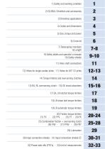
1) Sicurezza and working di utilizzo 1) Safety e condizioni condition 2) GLOBAL Drivelines and accessories 2) Progetto GLOBAL 3) Caratteristiche applicative 3) Drivelines applications 4) Identificazione e4) Codes and dimensions composizione del codice 5) Dimensioni, Coppie, Potenze 5) Size, torque and power 6) Cross kit 6) Crociere 7)7) Elementi telescopici Telescoping members 8) Lunghezza 8) Length 9) Etichette dilabels and e manuali di utilizzo 9) Safety sicurezza operator’s manuals 10) Protezione antinfortunistica 10) Safety shields 11) 11) Sistemiconnections Yoke-shaft di fissaggio 12) Forcelle...
Open the catalog to page 3
© BONDIOLI & PAVESI SpA No part of this manual may be reproduced without specific permission from Bondioli & Pavesi. All data and codes contained in this catalog replace and supersede any information given by previous publications. Consequently data provided in previous publications may no longer be valid. Bondioli & Pavesi reserves the right to change specifications without prior notice or obligation.
Open the catalog to page 4
Index Safety and working conditions…………………………………………………………… 1. Sicurezza e condizioni di utilizzo……………………………………………………… 1.1 2. Progetto GLOBAL……………………………………………………………………… GLOBAL Drivelines and accessories…………………………………………………… 2.1 Cross kits: designed costruite per l’agricoltura……………………………………… Crociere progettate eand built for farming applications……………………………… 2.2 End yokes……………………………………………………………………………… Forcelle di estremità…………………………………………………………………… 2.4 Safety schields………………………………………………………………………… Protezione antinfortunistica…………………………………………………………… 2.8 Constant velocity joints: high efficiency, low...
Open the catalog to page 6
Index Driveline length……………………………………………………………………………… 8. Lunghezza……………………………………………………………………………… 8.1 Triangle profile ………………………………………………………………………… Tubi Triangolari…tubes…………………………………………………………………… 8.2 Splined telescoping members………………………………………………………… Telescopi scanalati……………………………………………………………………… 8.3 Safety labels di sicurezza e manuale di utilizzo………………………………………… 9.1 9. Etichette and operator’s manuals…………………………………………………… 10. Protezione antinfortunistica…………………………………………………………… Safety shields……………………………………………………………………………… 10.1 Technical data…………………………………………………………………………… Caratteristiche tecniche…………………………………………………………………...
Open the catalog to page 7All BONDIOLI & PAVESI catalogs and technical brochures
 1000 SERIES
16 Pages
 S2003 series
36 Pages
 S2001 series
36 Pages
 SFT series
36 Pages
 Aluminium Heat Exchanger | A86
10 Pages
 Aluminium Heat Exchanger | A26
11 Pages
 Aluminium Heat Exchanger | A31
11 Pages
 Aluminium Heat Exchanger | A35
11 Pages
 Aluminium Heat Exchanger | A46
11 Pages
 Aluminium Heat Exchanger | A48
11 Pages
 Aluminium Heat Exchanger | A50
11 Pages
 Aluminium Heat Exchanger | A56
11 Pages
 Aluminium Heat Exchanger | A60
11 Pages
 Aluminium Heat Exchanger | A65
11 Pages
 Aluminium Heat Exchanger | A70
11 Pages
 Aluminium Heat Exchanger | A75
11 Pages
 Aluminium Heat Exchanger | A80
10 Pages
 Aluminium Heat Exchanger | A83
10 Pages
 Electronic Joystick - HPEJ
5 Pages
 Grips - HPCI
23 Pages
 Fan Drive Systems
22 Pages
 Electronic Control Unit
18 Pages
 Multiple Pumps
4 Pages
 Silent Gear Pumps
34 Pages
 Standard Gearboxes - 2000 series
44 Pages
 Standard Gearboxes - 4000 series
20 Pages
 Standard Gearboxes - 3000 series
24 Pages
 Standard Gearboxes - 2001 series
48 Pages
 Standard Gearboxes - 1000 series
16 Pages
 SFT 017 Catalog
728 Pages
 DC013
DC013124 Pages








Archived catalogs
 SC013
SC01368 Pages
 GL013
GL01390 Pages
 AM013
AM01326 Pages
 BA013
BA01360 Pages
 GM013
GM01334 Pages
 OP013
OP01384 Pages
 QH012
QH0121298 Pages
 SM013
SM01351 Pages
 Group presentation
2 Pages
 BIMA013
100 Pages
 S012 - BIMA
157 Pages
 S012 parte1
197 Pages
 S012
S012354 Pages
 Gearboxes / Paralle
223 Pages
 Fan Drive Systems
28 Pages
 Input implement connection shields
15 Pages
 PTO Driveshaft
250 Pages


- Directional control valve
- Hydraulic pump
- Servo-motor
- Heat exchanger unit
- Gear train gear reducer
- Transmission gearhead
- Hydraulic directional control valve
- Liquid/liquid heat exchanger
- High-performance servo motor
- Hydraulic piston pump
- Spool hydraulic directional control valve
- Plate heat exchanger
- Tubular heat exchanger
- Controller servomotor
- Parallel-shaft gearhead
- Multi-channel manifold
- Hydraulic motor
- BLDC servomotor
- Hydraulic gear pump