
- Catalogs
- BONDIOLI & PAVESI
- Fan Drive Systems

Fan Drive Systems

Fan Drive Systems
The HP Hydraulic Fan Drive systems offer integrated cooling solutions using hydraulic motors to drive fans, independent of the thermal motor speed. Each kit includes a hydraulic motor, electronic control unit (ECU), wiring, and temperature sensors. The system ensures precise temperature control and features a fail-safe mode for maximum fan speed during electronic failures. It supports PC connectivity for calibration and diagnostics.
The ECU controls solenoid valves based on temperature signals, allowing efficient fan speed management. It supports up to four temperature signals and can reverse fan direction for radiator cleaning. The system includes sensors and wiring harnesses essential for operation.
Guidelines are provided for connecting the ECU to a PC for calibration and diagnostics. The fail-safe feature ensures maximum fan speed if electronic failure occurs.
Details are provided for ordering motors and electronic boards to ensure correct component selection for specific applications.
The system activates solenoid valves only when all temperatures are below a set threshold. It manages up to four temperature signals, each requiring a specific sensor.
The system includes a retarder function for solenoid valve deactivation and allows fan rotation inversion for radiator cleaning, either automatically or manually.
The RS-232 interface connects the ECU to a PC for parameter calibration using HP Hydraulic ECUTuner software. Accessories include sensors and standard cabling.
Specifications for power supply voltage, operating/storage temperatures, protection class, and solenoid valve details are provided.
Technical specifications include operating temperature ranges, maximum current, PWM frequency, and protection classes. Pinout details for the SE11 ECU and descriptions of temperature sensors and wiring systems are included.
Connection details for the electronic control system, including temperature sensors, solenoid valves, digital inputs/outputs, and power supply connections, are specified.
Programming requires a PC connection using the HPEATOOL kit.
Standard wiring configurations for the fan drive application are provided, detailing connections for the ECU, sensors, solenoid valves, and power supply.
Catalog excerpts

- BONDIOLI LSI A & PAVESI l5J w mmiM.iurrm SISTEMI FAN DRIVE FAN DRIVE SYSTEMS
Open the catalog to page 1
INDICE INDEX INHALTSVERZEICHNIS INTRODUZIONE INTRODUCTION EINLEITUNG COMPONENTI ELETTRONICI ELECTRONIC COMPONENTS 8 ELEKTRONISCHE BAUELEMENTE ISTRUZIONI GENERALI DI IMPIEGO OPERATING INSTRUCTIONS 10 ALLGEMEINE GEBRAUCHSANWEISUNGEN VERSIONI VERSIONS VERSION ISTRUZIONI PER L'ORDINAZIONE (MOTORE) ORDERING INSTRUCTIONS (MOTOR) 1 8 BESTELLSCHLUSSEL (MOTOR) ISTRUZIONI PER L'ORDINAZIONE (SCHEDE ELETTRONICHE) ORDERING INSTRUCTIONS (ELECTRONIC BOARDS) BESTELLSCHLUSSEL FUR MIKROCONTROLLER (ELEKTRONIKKARTE) ACCESSORI ELETTRONICI - SENSORI ELECTRONIC ACCESSORIES - SENSORS 20 ELEKTRONISCHES ZUBEHOR...
Open the catalog to page 2
INTRODUZIONE INTRODUCTION EINLEITUNG BONDIOLI LSI A & PAVESI l5J w mmiM.iurrm I sistemi Fan Drive di HP Hydraulic offrono soluzioni integrate per sistemi di raffreddamento basati su: • scambiatori di calore standard olio aria; • radiatori combinati acqua olio e intercooler dotati di ventola azionata da motore idraulico, per applicazioni oleodinamiche mobili. Ogni kit comprende: • motore idraulico; • centralina elettronica di controllo con relativo cablaggio; • sensori di temperatura. La centralina elettronica pilota, sulla base dei segnali di temperatura acquisiti dal sistema, le elettrovalvole...
Open the catalog to page 3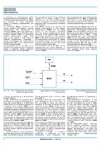
II principio di funzionamento della centralina elettronica e illustrato in in riferimento alla configurazione circuitale piu articolata tra quelle disponibili, dotata di comando proporzionale con inversione. La centralina (ECU) acquisisce dai sensori installati nell’impianto i segnali corrispondenti alle temperature di interesse (TEMP) e gli input digitali per i comandi dell’operatore: attivazione della funzione retarder (RET) e attivazione forzata dell’inversione sulla base di tali segnali e della logica di controllo programmata, costruisce i segnali di pilotaggio per l’elettrovalvola proporzionale...
Open the catalog to page 4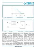
Fig. 2 - Fig. 2 - Abb. 2 Controllo proporzionale Proportional fan speed control Proportionale Lufterregelung della velocita della ventola della regolazione di tale temperatura in relazione alle altre; tale coefficiente e utilizzato per calcolo la media ponderata delle correnti I. • valore minimo: la corrente IS coincide con la minima tra le correnti I: in questo modo il sistema risponde in ogni istante fornendo la velocita di rotazione massima tra quelle richieste. La corrente IS precedentemente calcolata e infine elaborata da un ulteriore blocco logico (L): in caso di attivazione della funzione...
Open the catalog to page 5
quanto sopra descritto. La corrispondenza tra temperatura T e corrente I assume la caratteristica riportata in Fig.4: I’output assume esclusivamente i 2 valori discreti possibili: eccitazione dell’elettrovalvola impone la velocita minima della ventola) e diseccitazione (OFF che impone la velocita massima), secondo una caratteristica con isteresi. The correspondence between temperature T and current I assumes the characteristic in the output only assumes the 2 discrete values possible: excited solenoid valve (ON, which translates into the minimum speed of the fan) and deactivation of the...
Open the catalog to page 6
PROGRAMMAZIONE PROGRAMMING PROGRAMMIERUNG BONDIOLI LSI A & PAVESI l5J w mmiM.iurrm L’interfaccia di comunicazione RS-232 permette la connessione della centralina a un PC dotato di software ECUTuner di HP Hydraulic. ECUTuner e un tool utilizzato per la calibrazione dei parametri di controllo; tra i parametri regolabili abbiamo: • il tipo di sensore di temperatura installato su ogni canale di input; • i valori di soglia per ogni temperatura acquisita; • le correnti di pilotaggio delle elettrovalvole; • l’entita di correzione imposta dalla funzione retarder; • la frequenza e la durata dell’inversione di...
Open the catalog to page 7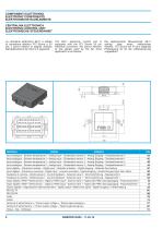
COMPONENT! ELETTRONICI ELECTRONIC COMPONENTS ELEKTRONISCHE BAUELEMENTE CENTRALINA ELETTRONICA ELECTRONIC CONTROL UNIT ELEKTRONISCHE STEUEREINHEIT La centralina elettronica SE11 e dotata di connettore elettrico FCI Sicma a 24 pin; il pinout relativo ai segnali utilizzati dall’applicazione fan drive e il seguente: The SE11 electronic control unit is equipped with the FCI Sicma 24 pin electrical connector; the pinout relevant to the signals used by the fan drive application is as follows: Die elektronische Steuereinheit SE11 verfugt uber einen elektrischen Stecker FCI Sicma mit 24 pin; folgende Pinbelegung...
Open the catalog to page 8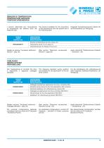
SENSORI DI TEMPERATURA TEMPERATURE SENSORS TEMPERATURSENSOREN I sensori disponibili per I’acquisizione The sensors available for the acquisition Folgende Temperatursensoren stehen fur di temperatura dal sistema sono del of the temperature from the system are of die Kuhlsysteme zur Verfugung: seguente tipo: the following type: (Vedere sezione “Accessori elettronici -Cablaggi standard”, pag. 22). Per eventuali configurazioni dedicate, contattare il servizio clienti di HP Hydraulic - Bondioli & Pavesi. (See section “Electronic accessories -Standard wiring”, 22). For dedicated configurations,...
Open the catalog to page 9
Caratteristiche elettriche generali / General electrical specifications I Allgemeine elektrische Daten
Open the catalog to page 10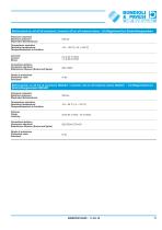
Elettrovalvole on-off 4/2 di inversione / Inversion 4/2 on-off solenoid valves /14/2-Magnetventil zur Drehrichtungsumkehr Pressione massima Maximum pressure 240 bar Maximaler Betriebsdruck Temperatura operativa Operating temperature -40 ^ 120 °C [-40 ^ 248 °F] Corrente Current Strom Connettore elettrico Connector electrical Elektrischer Stecker (Sockel auf Spule) Grado di protezione Protection class IP 65 Elettrovalvole on-off 4/2 di inversione ISO4401 / Inversion 4/2 on-off solenoid valves ISO4401 Zt4/2-Magnetventil zur Drehrichtungsumkehr ISO4401 Pressione massima Maximum pressure 250...
Open the catalog to page 11
VERSIONI VERSIONS VERSION CONFIGURAZIONE “V1”: ON-OFF CON ANTICAVITAZIONE “V1” CONFIGURATION: ON-OFF WITH ANTICAVITATION KONFIGURATION “V1”: MOTOR MIT S/W-MAGNETVENTIL, MAX.DBV UND NACHSAUGVENTIL Velocità ventola Fan speed Lüfterdrehzahl Velocità motore endotermico Endothermic motor speed Drehzahl Brennkraftmaschine DIMENSIONI SIZE ABMESSUNGEN E2 GRUPPO GROUP BAUREIHE E2 = Vedi sezione flange F2 = Vedi profilo alberi E2 = See flange section F2 = See shafts profile E2 = siehe Abschnitt “Flansche” F2 = siehe Abschnitt “Wellenende”
Open the catalog to page 12All BONDIOLI & PAVESI catalogs and technical brochures
 1000 SERIES
16 Pages
 S2003 series
36 Pages
 S2001 series
36 Pages
 SFT series
36 Pages
 Aluminium Heat Exchanger | A86
10 Pages
 Aluminium Heat Exchanger | A26
11 Pages
 Aluminium Heat Exchanger | A31
11 Pages
 Aluminium Heat Exchanger | A35
11 Pages
 Aluminium Heat Exchanger | A46
11 Pages
 Aluminium Heat Exchanger | A48
11 Pages
 Aluminium Heat Exchanger | A50
11 Pages
 Aluminium Heat Exchanger | A56
11 Pages
 Aluminium Heat Exchanger | A60
11 Pages
 Aluminium Heat Exchanger | A65
11 Pages
 Aluminium Heat Exchanger | A70
11 Pages
 Aluminium Heat Exchanger | A75
11 Pages
 Aluminium Heat Exchanger | A80
10 Pages
 Aluminium Heat Exchanger | A83
10 Pages
 Electronic Joystick - HPEJ
5 Pages
 Grips - HPCI
23 Pages
 Electronic Control Unit
18 Pages
 Multiple Pumps
4 Pages
 Silent Gear Pumps
34 Pages
 Standard Gearboxes - 2000 series
44 Pages
 Standard Gearboxes - 4000 series
20 Pages
 Standard Gearboxes - 3000 series
24 Pages
 Standard Gearboxes - 2001 series
48 Pages
 Standard Gearboxes - 1000 series
16 Pages
 Global 017 Catalog
308 Pages
 SFT 017 Catalog
728 Pages
 DC013
DC013124 Pages







Archived catalogs
 SC013
SC01368 Pages
 GL013
GL01390 Pages
 AM013
AM01326 Pages
 BA013
BA01360 Pages
 GM013
GM01334 Pages
 OP013
OP01384 Pages
 QH012
QH0121298 Pages
 SM013
SM01351 Pages
 Group presentation
2 Pages
 BIMA013
100 Pages
 S012 - BIMA
157 Pages
 S012 parte1
197 Pages
 S012
S012354 Pages
 Gearboxes / Paralle
223 Pages
 Fan Drive Systems
28 Pages
 Input implement connection shields
15 Pages
 PTO Driveshaft
250 Pages

- Directional control valve
- Hydraulic pump
- Servo-motor
- Heat exchanger unit
- Gear train gear reducer
- Transmission gearhead
- Hydraulic directional control valve
- Liquid/liquid heat exchanger
- High-performance servo motor
- Hydraulic piston pump
- Spool hydraulic directional control valve
- Plate heat exchanger
- Tubular heat exchanger
- Controller servomotor
- Parallel-shaft gearhead
- Multi-channel manifold
- BLDC servomotor
- Friction clutch
- Hydraulic gear pump