- Catalogs
- Bolte GmbH
- WELDING STUDS FOR DRAWN ARC STUD WELDING WITH SHIELDING GAS
WELDING STUDS FOR DRAWN ARC STUD WELDING WITH SHIELDING GAS
1 /16Pages

WELDING STUDS FOR DRAWN ARC STUD WELDING WITH SHIELDING GAS
1 /16Pages
Catalog excerpts
WELDING STUDS FOR DRAWN ARC STUD WELDING WITH SHIELDING GAS
Open the catalog to page 1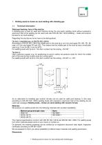
1. Welding studs for drawn arc stud welding with shielding gas 1.1 Technical information Weld pool backing, form of the stud tip If shielding gas is used for weld pool backing during the stud weld, welding studs without pressed-in aluminium ball at the welding tip are used (see also DIN EN ISO 13918 Welding – Studs and ceramic ferrules for arc stud welding). Regarding the stud tip two forms have to be distinguished. Tip form 1 (standard acc. to DIN EN ISO 13918): According to DIN EN ISO 13918 the middle part of the stud tip is d2/3 (for stud types RD, MD, PD, ID) resp. d1/3 (for stud types FD...
Open the catalog to page 5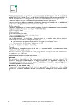
Welding studs dimensions are given in the measurement tables (all dimensions in mm). All standardised welding studs conform to DIN EN ISO 13918. Not standardised welding studs are supplied according to DIN EN ISO 13918. Special welding elements, which are not described, are delivered upon request. Dimensions that are not listed in the measurement tables are delivered upon request. The nominal length (l2) always corresponds to the length after welding. Depending on the diameter the length before welding (l1) is larger by a weld allowance of 1 to 5 mm. Surface protection Usually our welding studs...
Open the catalog to page 6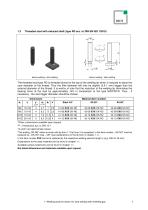
Threaded stud with reduced shaft (type RD acc. to DIN EN ISO 13918) before welding / after welding before welding / after welding The threaded stud type RD is threaded almost to the top of the welding tip which is reduced to about the core diameter of the thread. Thus the fillet diameter will only be slightly (0,5-1 mm) bigger than the external diameter of the thread. It is worthy of note that the reduction of the welding tip diminishes the bearing force of the stud by approximately 15% in comparison to the type MD/PD/FD. Thus - if necessary - the next bigger diameter should be chosen. Dimensions...
Open the catalog to page 7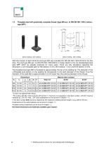
Threaded stud with practically complete thread (type MD acc. to DIN EN ISO 13918, before: type MPF) before welding / after welding before welding / after welding With the revision of April 2018 the stud type MD was included into DIN EN ISO 13918:2018 for the first time. The stud type MD acc. to DIN EN ISO 13918:2018 is mostly identic to the not standardised stud type MPF which we already produced for many years. There are only deviations regarding the dimension y (non-threaded part) for M6 (before: 3 mm), M10 (before: 7 mm) and M12 (before: 8 mm). The threaded stud type MD is threaded to approximately...
Open the catalog to page 8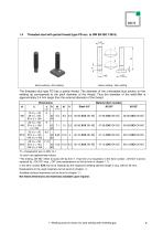
Threaded stud with partial thread (type PD acc. to DIN EN ISO 13918) before welding / after welding before welding / after welding The threaded stud type PD has a partial thread. The diameter of the unthreaded stud section on the welding tip corresponds to the pitch diameter of the thread. Thus the diameter of the weld-fillet is approximately 3-4 mm larger than the external diameter of the thread. Dimensions d1 Material (item number) d2 = thread pitch acc. to DIN 13-1 *d3 and h are approximate values. 2The ending „OK-NÜ“ refers to studs with tip form 1. If tip form 2 is requested, in the item...
Open the catalog to page 9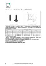
Threaded stud with full thread (type FD acc. to DIN EN ISO 13918) before welding / after welding before welding / after welding The threaded stud type FD is threaded to the top of the welding tip. Thus after welding the stud is threaded up to the weld-fillet. The diameter of the weld-fillet is approximately 3-4 mm larger than the external diameter of the thread. Dimensions Material (item number) * *d3 and h are approximate values. 1The ending „OK-NÜ“ refers to studs with tip form 1. If tip form 2 is requested, in the item number „-OK-NÜ“ must be replaced by „-OK-SÜ“ resp. „-OK“ (see explanations...
Open the catalog to page 10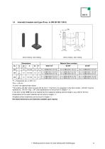
Internally threaded stud (type ID acc. to DIN EN ISO 13918) before welding / after welding before welding / after welding Material (item number) = thread pitch acc. to DIN 13-1 for l2 < 20 mm *d3 and h are approximate values. 2The ending „OK-NÜ“ refers to studs with tip form 1. If tip form 2 is requested, in the item number „-OK-NÜ“ must be replaced by „-OK-SÜ“ resp. „-OK“ (see explanations on the tip form in chapter 1.1). In the item number XXX has to be replaced by the respective welding element length l 2 (e.g. 030 for 30 mm). Explanations to the used materials can be found in chapter 1.1....
Open the catalog to page 11
Non-threaded stud (type UD acc. to DIN EN ISO 13918) before welding / after welding before welding / after welding Material (item number) *d2 and h are approximate values. 1The ending „OK-NÜ“ refers to studs with tip form 1. If tip form 2 is requested, in the item number „-OK-NÜ“ must be replaced by „-OK-SÜ“ resp. „-OK“ (see explanations on the tip form in chapter 1.1). In the item number XXX has to be replaced by the respective welding element length l 2 (e.g. 030 for 30 mm). Explanations to the used materials can be found in chapter 1.1. Available surface treatments can be found in chapter...
Open the catalog to page 12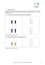
Silicone cover caps Silicone cover caps protect the mechanical important areas of the welding elements during painting and powder coating as well as during the burning-in process (permanent temperature ≤ 210° C, short temperature ≤ 300° C). 1.8.1 Silicone cover caps for threaded studs and non-threaded studs Available dimensions upon request. 1.8.2 Silicone cover caps for internally threaded studs Available dimensions upon request. 1. Welding studs for drawn arc stud welding with shielding gas
Open the catalog to page 13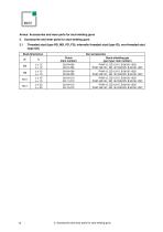
Annex: Accessories and wear parts for stud welding guns 2. Accessories and wear parts for stud welding guns 2.1 Threaded stud (type RD, MD, PD, FD), internally threaded stud (type ID), non-threaded stud (type UD) Stud dimensions Chuck (item number) Stand shielding gas (gun type: item number) 2. Accessories and wear parts for stud welding
Open the catalog to page 14
© Bolte GmbH Last update 09/18. Texts and illustrations correspond with technical standard at the date of printing. Errors and omissions excepted.
Open the catalog to page 16All Bolte GmbH catalogs and technical brochures
 ZUBEHÖR ACCESSORIES
104 Pages
 PKA-500 PHA-500 PHA-500-6
4 Pages
 VBZ
VBZ4 Pages
 KKA-200F KHA-200F
4 Pages
 SERIES V
6 Pages
 SERIES T
6 Pages
 PIM-1B PIM-1K
4 Pages
 PKM-1B PHM-1A
4 Pages
 GD
GD6 Pages
 PHM
PHM4 Pages
 LBS
LBS6 Pages
 PRO-S
PRO-S6 Pages
 PRO-I
PRO-I8 Pages
 PRO-D
PRO-D6 Pages
 SHEAR CONNECTORS
4 Pages
 BOLTE GmbH
6 Pages


- Welding system
- Automatic welding machine
- Welder
- Feeder
- Manual gun
- Arc welder
- Portable welder
- Arc welding machine
- Precision welding machine
- Inverter welder
- Automated feeder
- DC welder
- Automatic gun
- 230V single phase welding machine
- CNC welding machine
- Pneumatic sealer
- Pneumatic gun
- Steel welder
- Benchtop welding machine
- Power adapter