Type WPM Filtered PWM Speed Controls for Permanent Magnet DC Brush Motors Models 0790 & 0791, NEMA 1 enclosure
2Pages

Catalog excerpts

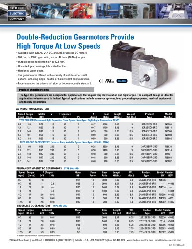
Instructions for Installation and Operation Type WPM Filtered PWM Speed Controls for Permanent Magnet DC Brush Motors • Models 0790 & 0791, NEMA 1 enclosure FIGURE 1–Control mounting dimensions Acceleration/Deceleration Time Means for Speed Adjustment Means for Drive Inhibit Diagnostics Input Voltage Maximum Input Current, Continuous Model 0790 Model 0791 Output Voltage Ambient Temperature Maximum Output Current, Continuous Model 0790 Model 0791 Maximum Output Current, Peak Model 0790 Model 0791 Speed Regulation BODINE ELECTRI C COMPANY DC motor speed control C 2.00 Amps DC* 3.20 Amps DC 2.20 Amps DC 5.00 Amps DC 1% of rated speed obtainable with most motors Adjustable, 0.1-15 seconds 10K Ohm potentiometer switch closure green power LED, red current limit LED RoHS COMPLIANT FIGFIGURE 2–Setup of Dip Switches 1 through 6 * Thermal rating only. Actual max. continuous output current is 1.25 Amps. WARNING: This control should only be installed by a qualified person familiar with its operation and associated hazards. The National Electrical Code (NEC), local electrical and safety codes, and when applicable, the Occupational Safety and Health Act (OSHA) should be observed to reduce hazards to personnel and property. Step 1: Mounting the Control The control may be mounted using any two or all four mounting holes. The mounting holes have clearance for 1/4-20 or M6 screws. Step 2: Preliminary Setup HORSEPOWER & ACCELERATION SELECTOR SWITCHES–Control models 0790 and 0791 are packaged with the enclosure cover unattached. Remove the cover to set the horsepower and acceleration selector switches. Figure 4 shows the location of a bank of 8 dip switches. Set switches 1 through 6 to match the type, speed, and current ratings on the Bodine motor nameplate per Figure 2 (consult Bodine on settings for non-Bodine motors). Set switches 7 and 8 to select the acceleration/ deceleration time range per Figure 3. Step 3: Electrical Connections The enclosure cover must be removed as shown in Figure 4 to make the electrical connections. WARNING–All parts of the circuit operate at voltages capable of causing serious injury or death. WARNING–The AC power line to the control should be the last connection made. CAUTION–The control board signal common is not at ground potential. Any external signal or equipment connected to the control must be electrically isolated from ground. INHIBIT SWITCH (OPTIONAL)–A mechanical switch or relay with contacts rated for low voltage may be connected to terminals “H1” and “H2”. With the switch open, the motor will run. With the switch closed, the motor will coast to a stop. WARNING–The inhibit switch should not be used to disable motor or control when servicing these or driven equipment. Disconnect the AC power instead. FIGURE 3–Setup of dip switches 7 and 8 Switches Acceleration/Deceleration Time Range (seconds)6 7 8 ACC pot fully CCW (factory setting) ACC pot fully CW Off Off .1 .3 Off On .5 2.0 On Off 3.5 12.0 On On 4.0 15.0 1. or armature speed of a geared motor, multiply the output speed at the driveshaft by the F gear ratio. 2. f the user desires to install their own armature fuse on the control output to protect the motor I from continuous overloads, base fuse ratings on the motor rating in this column. 3. Peak current available with TORQ pot in fully CW position (factory setting). This current exceeds the continuous rating of the motor and is for intermittent overload conditions only. 4. se this column for sizing a line fuse on the control input. U 5. he REG potentiometer must be turned fully CCW (off) for high-speed type 24ABEPM motor. T 6. ime for voltage across A1 and A2 to ramp up to 130 V when speed pot is turned from 0 to 100; T or to ramp down to 0 V when it is turned from 100 to 0. The time for a motor to accelerate from 0 to 2500 rpm or decelerate from 2500 to 0 rpm is dependent on motor size and loading conditions. 201 Northfield Road | Northfield Illinois, 60093, U.S.A. | Phone 773.478.3515 | www.bodine-electric.com | info@bodine-
Open the catalog to page 1
INSTALLATION, continued MOTOR CONNECTIONS–Feed the motor cable through the opening in the bottom of the enclosure. For clockwise armature rotation, connect the “+” motor wire (white wire on Bodine motors) to terminal “A2” and the “–” motor wire (black wire on Bodine motors) to terminal “A1”. For counterclockwise rotation, reverse the motor connections. Reinstall enclosure cover. LINE FUSE–Models 0790 and 0791 are equipped with a fuseholder on the front panel that is accessible to users for field replacement of the fuse. A four amp fuse is factory installed in model 0790 and an eight amp...
Open the catalog to page 2All BODINE ELECTRIC COMPANY catalogs and technical brochures
-
 PLANETARY BLDC GEARMOTORS
2 Pages
-
 Standard Products
4 Pages
-
 Bodine Electric Handbook
252 Pages
-
 42R-FX AC Gearmotor
2 Pages
-
 DC control selection guides
12 Pages
-
 AC control selection guides
3 Pages