
- Catalogs
- BODINE ELECTRIC COMPANY
- OEM Series Chassis/IP-20 AC Drives


- Company
- Products
- Catalogs
- News & Trends
- Exhibitions
OEM Series Chassis/IP-20 AC Drives
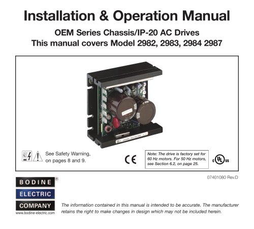
OEM Series Chassis/IP-20 AC Drives
- Adjustable RMS Current Limit and I2t Motor Overload Protection ensure motor safety and efficiency.
- Slip Compensation with Static Auto-Tune and Boost offers high torque and load regulation over a wide speed range.
- Power Start™ delivers over 200% motor torque for high frictional load startups.
- Electronic Inrush Current Limit (EICL™) prevents harmful AC line inrush current.
- Drive-Link™ software allows programming for DC Injection Braking.
- Simple operation with factory-set trimpots and jumpers.
- Diagnostic LEDs for power and drive status.
- Jumper selection for drive output frequency to increase motor speed.
- Industry-standard mounting and IP-20 Finger-Safe Cover for safety.
- Power Start™ ensures startup of high frictional loads with more than 200% starting torque.
- Slip Compensation provides excellent load regulation over a wide speed range.
- Speed range capability of 60:1.
- Motor Overload (I2t) with RMS Current Limit prevents motor burnout and nuisance trips.
- Electronic Inrush Current Limit (EICL™) eliminates harmful inrush AC line current.
- Short Circuit protection prevents drive failure.
- Motor Filter reduces harmful voltage spikes.
- Regeneration eliminates nuisance tripping due to bus overvoltage.
- Undervoltage and Overvoltage protection shuts down the drive if input voltage is out of range.
- Minimum and Maximum Speed settings.
- Acceleration and Deceleration time settings.
- Slip Compensation and Boost settings for optimal performance.
- Current Limit settings to control maximum motor current.
- Guidance on using motors with external fan cooling to prevent overheating.
- Recommendations for using inverter duty or TENV motors for extended speed range without overheating.
- Instructions for removing and installing the Finger-Safe Cover to prevent accidental contact with high voltage.
- Guidelines for setting selectable jumpers for AC line input voltage and motor operation frequency.
- Manual Restart: After a prolonged overload, the drive requires a manual restart.
- Speed Selection: The drive is factory set for Forward Speed Operation. For Reverse Speed Operation, adjust the jumper on CON2.
- Mounting Instructions: The drive must be mounted in an enclosure to prevent damage from environmental factors.
- Hi-Pot Testing: Recommended procedure to prevent damage during high voltage testing.
- Wiring Instructions: Follow safety warnings and ensure proper grounding.
- AC Line Connection: Wire single-phase AC line input to Terminals "L1" and "L2".
- Motor Connection: Connect motor to Terminals "U", "V", "W".
- Manual Start Switch: For manual start mode, remove the factory jumper on CON1 and install a momentary switch.
- Start-Up Procedure: Ensure all settings and wiring are complete before starting.
- Fault Recovery: The drive monitors faults such as Undervoltage, Overvoltage, Short Circuit, and I2t.
- Power On LED: Indicates power status.
- Status LED: Provides fault and operational status indications.
- Minimum Speed (MIN): Adjusts the minimum speed of the motor.
- Maximum Speed (MAX): Sets the maximum speed of the motor.
- Acceleration (ACC): Controls the time for the motor to accelerate from zero to full speed.
- Deceleration (DEC/B): Sets the time for the motor to decelerate from full speed to zero.
- Slip Compensation (COMP): Adjusts Volts/Hz to maintain motor speed under varying loads.
- Boost (DEC/B): For 50 Hz motor operation, adjusts the boost to optimize motor performance.
- Motor Overload (I2t) with RMS Current Limit (CL): Sets the current limit to prevent motor burnout.
- For high inertial loads, set ACC and DEC/B Trimpots to greater than 10 seconds to prevent overvoltage.
- In 50 Hz motor operation, ensure boost is adjusted properly to avoid motor winding heating.
- Bodine Electric Company provides a warranty for products free of defects in workmanship and materials when used according to specifications. The warranty period is 24 months from purchase or 30 months from manufacture for Bodine motors and gearmotors used with Bodine controls, and 12 months for other combinations.
- Warranty claims require proof of purchase and are limited to repair, replacement, or refund.
Catalog excerpts
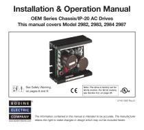
Installation & Operation Manual OEM Series Chassis/IP-20 AC Drives This manual covers Model 2982, 2983, 2984 2987 See Safety Warning, on pages 8 and 9. Note: The drive is factory set for 60 Hz motors. For 50 Hz motors, see Section 6.2, on page 25. The information contained in this manual is intended to be accurate. The manufacturer retains the right to make changes in design which may not be included herein.
Open the catalog to page 1
TABLE OF CONTENTS Section Page 1 Quick-Start Instructions . . . . . . . . . . . . . . . . . . . . . . . . . . . . . . . . . . . . . . . . . . . . . . . . . . . . . . 6 – 8 2 Safety Warning . . . . . . . . . . . . . . . . . . . . . . . . . . . . . . . . . . . . . . . . . . . . . . . . . . . . . . . . . . . . . 8 – 9 3 Introduction. . . . . . . . . . . . . . . . . . . . . . . . . . . . . . . . . . . . . . . . . . . . . . . . . . . . . . . . . . . . . . . 9 – 20 4 Important Application Information . . . . . . . . . . . . . . . . . . . . . . . . . . . . . . . . . . . . . . . . . . . . . 20 – 22 5...
Open the catalog to page 2
TABLE OF CONTENTS (Continued) Figure Page 3A Model 2987 Mechanical Specifications . . . . . . . . . . . . . . . . . . . . . . . . . . . . . . . . . . . . . . . . . . . . . 18 3B Models, 2987 Mechanical Specifications. . . . . . . . . . . . . . . . . . . . . . . . . . . . . . . . . . . . . . . . . . . . 19 4 Expanded View of Jumpers and Trimpots . . . . . . . . . . . . . . . . . . . . . . . . . . . . . . . . . . . . . . . . . . . 20 5 Maximum Allowed Motor Torque vs. Speed . . . . . . . . . . . . . . . . . . . . . . . . . . . . . . . . . . . . . . . . . 21 6 Open Ventilated Motor with External...
Open the catalog to page 3
TABLE OF CONTENTS (Continued) Figure Page 27 Boost Trimpot (DEC/B) Range . . . . . . . . . . . . . . . . . . . . . . . . . . . . . . . . . . . . . . . . . . . . . . . . . . . 40 30 Models 2982, 2983, 2984 Current Limit Trimpot (CL) Range . . . . . . . . . . . . . . . . . . . . . . . . . . . . 43 31 Models 2987 Current Limit Trimpot (CL) Range . . . . . . . . . . . . . . . . . . . . . . . . . . . . . . . . . . . . . . 43 Items Included in this Package: Bodine Adjustable Frequency Drive, Bodine Series Installation and Operation Manual, Main Speed Potentiometer Kit with Insulator and Mounting Hardware,...
Open the catalog to page 4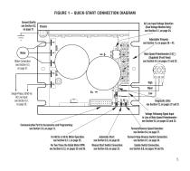
FIGURE 1 – QUICK-START CONNECTION DIAGRAM Ground (Earth): see Section 9.2, on page 31. AC Line Input Voltage Selection (Dual Voltage Models Only): see Section 6.1, on page 24. Main Speed Potentiometer (5 KW ) (Supplied) (Front View): see Section 9.4, on pages 31 and 32. Motor Connection: see Section 9.3, on page 31. Adjustable Trimpots: see Section 13, on pages 38 – 43. High Wiper Single-Phase, 50/60 Hz AC Line Input: see Section 9.1, on page 30. Diagnostic LEDs: see Section 12, on pages 37 and 38. Voltage Following Signal Input in Lieu of Main Speed Potentiometer: see Section 9.5, on pages 32...
Open the catalog to page 5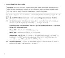
QUICK-START INSTRUCTIONS Important – You must read these simplified instructions before proceeding. These instructions are to be used as a reference only and are not intended to replace the details provided herein. You must read the Safety Warning on, pages 8 and 9, before proceeding. See Figure 1 on page 5. Also see Section 4 – Important Application Information, on pages 20 – 22. WARNING! Disconnect main power when making connections to the drive. 1.1 AC Line Connection – Wire the single-phase AC line input to Terminals “L1” and “L2”, as shown in Figure 16, on page 31. See Section 9.1, on pages...
Open the catalog to page 6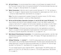
AC Line Fusing – It is recommended that a fuse(s) or circuit breaker be installed in the AC line. Fuse each conductor that is not at ground potential. For the recommended fuse size, see Table 1, on page 14. Also see Section 10, on page 35. Motor Connection – Wire the motor to quick-connect Terminals “U”, “V”, “W”, as shown in Figure 16, on page 31. (Special reactors may be required for cable lengths over 100 ft. (30 m) – consult our Sales Department.) See Section 9.3, on page 31. Note: The drive is programmed to operate 3-phase AC induction motors. For PSC motors, optional software is required...
Open the catalog to page 7
Note: For signal following operation, the Minimum Speed Trimpot (MIN) must be set fully counterclockwise. WARNING! The signal input must be isolated from the AC line. Earth grounding signal wiring will damage the drive and void the warranty. It is recommended that the SIVFR — Signal Isolator and Run/Fault Relay be installed when using signal following. 2 SAFETY WARNING Definition of Safety Warning Symbols Electrical Hazard Warning Symbol – Failure to observe this warning could result in electrical shock or electrocution. Operational Hazard Warning Symbol – Failure to observe this warning could...
Open the catalog to page 8
This product should be installed and serviced by a qualified technician, electrician, or electrical maintenance person familiar with its operation and the hazards involved. Proper installation, which includes installation of the Finger-Safe Cover, wiring, mounting in proper enclosure, fusing or other current protection, and grounding can reduce the chance of electrical shocks, fires, or explosion in this product or products used with this product, such as electric motors, switches, coils, solenoids, and/or relays. Eye protection must be worn and insulated adjustment tools must be used when working...
Open the catalog to page 9
The Bodine Adjustable Frequency Drives provide variable speed control for standard 3-phase and Permanent Split Capacitor (PSC)1 AC induction motors from subfractional thru 11⁄2 HP. This manual covers models with single-phase AC line input only. The sine wave coded Pulse Width Modulated (PWM) output operates at a carrier frequency of 16 kHz, which provides high motor efficiency and low noise. Adjustable linear acceleration and deceleration are provided, making the drive suitable for soft-start applications. Due to its user-friendly design, the Bodine AC drive is easy to install and operate. Tailoring...
Open the catalog to page 10All BODINE ELECTRIC COMPANY catalogs and technical brochures
 Type ABL-3905 and ABL-3907
24 Pages
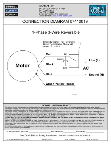 1-Phase 3-Wire Reversible
2 Pages
 Brushless DC Motor Control
24 Pages
 Type ABL-3906C Low-Voltage
20 Pages
 Models 0790 & 079
2 Pages
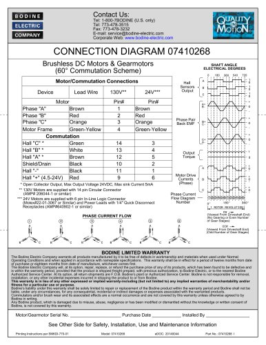 CONNECTION DIAGRAM 07410268
2 Pages
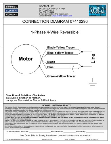 1-Phase 4-Wire Reversible
2 Pages
 STANDARD PRODUCTS 2025
52 Pages
 Bodine Electric Handbook
252 Pages

Archived catalogs
 PLANETARY BLDC GEARMOTORS
2 Pages
 IP-69K
2 Pages
 IP-66
2 Pages
 42R-5L/H
2 Pages
 33A7-WX
2 Pages
 34B-WX , 33A-WX
2 Pages
 42R-FX AC Gearmotor
2 Pages
 2998
2 Pages
 STANDARD PRODUCTS 2024
52 Pages






- DC electromotor
- Synchronous motor
- Bodine Electric gear-motor
- Electromotor for industrial applications
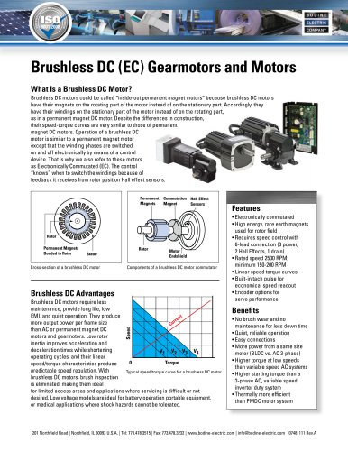
- EC motor
- Bodine Electric DC gear-motor
- Compact electromotor
- Permanent magnet motor
- Bodine Electric AC gear-motor
- Industrial electric gearmotor
- Bodine Electric right angle gear-motor
- Motor controller
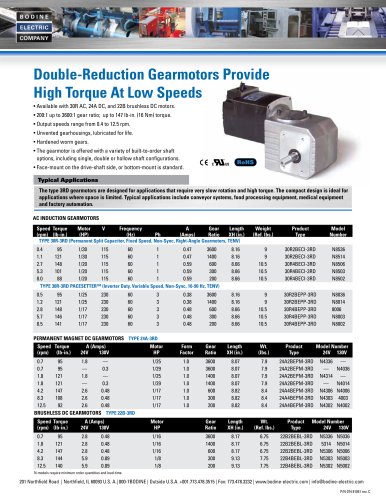
- Bodine Electric 24 V gear-motor
- Bodine Electric gear train gear-motor
- Planetary gearmotor
- Bodine Electric compact gear-motor
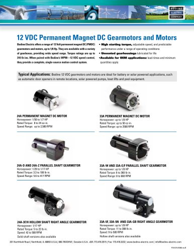
- 12 V electric gearmotor
- Bodine Electric low-noise gear-motor
- Bodine Electric parallel-shaft gear-motor