
- Catalogs
- BODINE ELECTRIC COMPANY
- Instructions for Installation and Operation


- Company
- Products
- Catalogs
- News & Trends
- Exhibitions
Instructions for Installation and Operation
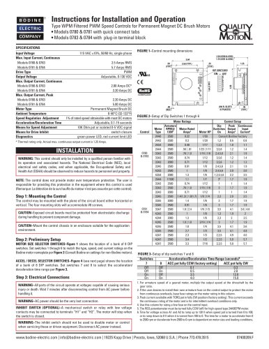
Instructions for Installation and Operation
- Input Voltage: 115 VAC ±10%, 50/60 Hz, single phase.
- Max Input Current: Models 0780 & 0783: 2.5 Amps RMS; Models 0781 & 0784: 5.7 Amps RMS.
- Output Voltage: Adjustable, 0-130 VDC.
- Max Output Current: Continuous: Models 0780 & 0783: 2.00 Amps DC; Models 0781 & 0784: 3.20 Amps DC. Peak: Models 0780 & 0783: 2.20 Amps DC; Models 0781 & 0784: 5.00 Amps DC.
- Motor Type: Permanent Magnet Brush DC.
- Ambient Temperature: 0-50°C (32-122°F).
- Speed Regulation: 1% of rated speed.
- Acceleration/Deceleration Time: Adjustable, 0.1-15 seconds.
- Mounting: The control can be mounted horizontally or vertically using #8 screws.
- Preliminary Setup: Set DIP switches for motor size and acceleration/deceleration time. Protect circuit boards from electrostatic discharge.
- Electrical Connections: Ensure all parts operate at safe voltages. Use an optional inhibit switch for motor stopping. AC power should be the last connection made.
- Preliminary Checks: Verify all connections and test the motor unloaded before proceeding with a load.
- Operating the Control: Set speed pot to "0" before turning on AC power. Adjust speed pot for desired motor speed.
- Trim Pot Adjustments: Use trim pots for fine-tuning speed limits, torque, and acceleration/deceleration times.
- Check diagnostic LEDs for power and current limit indications.
- Ensure proper fuse ratings and replace if necessary.
- Contact Bodine Authorized Service Center if issues persist.
Catalog excerpts
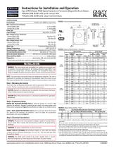
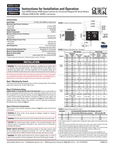
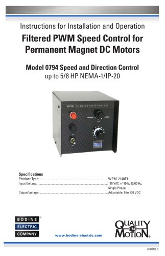
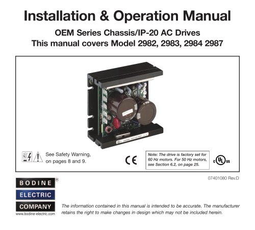
Instructions for Installation and Operation Type WPM Filtered PWM Speed Controls for Permanent Magnet DC Brush Motors • Models 0780 & 0781 with quick connect tabs • Models 0783 & 0784 with plug-in terminal block oy&piYMorloN. SPECIFICATIONS Input Voltage_ Max. Input Current, Continuous Models 0780 & 0783 Models 0781 & 0784_ Drive Type_ Output Voltage_ Max. Output Current, Continuous Models 0780 & 0783 Models 0781 & 0784_ Max. Output Current, Peak Motor Type_ Ambient Temperature_ Speed Regulation Adjustment Acceleration/Deceleration Time Means for Speed Adjustment Means for Drive Inhibit_ FIGURE 1-Control mounting dimensions _Permanent Magnet Brush DC 1% of rated speed obtainable with most DC motors _Adjustable, 0.1-15 seconds _switch closure _green power LED, red current limit LED * Thermal rating only. Actual max. continuous output current is 1.25 Amps. INSTALLATION WARNING: This control should only be installed by a qualified person familiar with its operation and associated hazards. The National Electrical Code (NEC), local electrical and safety codes, and when applicable, the Occupational Safety and Health Act (OSHA) should be observed to reduce hazards to personnel and property. NOTE: The control does not provide motor over temperature protection. The user is responsible for providing this protection in the equipment where this control is used (Remarque: La detection de la surchauffe du moteur n'est pas assuree par cette control). Step 1: Mounting the Control The control may be mounted with the plane of the circuit board either horizontal or vertical. The four mounting slots will accommodate #8 screws. CAUTION-Exposed circuit boards must be protected from electrostatic discharge during handling to prevent component damage. CAUTION-Mount the control chassis in an enclosure suitable for the application environment. Step 2: Preliminary Setup MOTOR SIZE SELECTOR SWITCHES-Figure 1 shows the location of a bank of 8 DIP switches. Set switches 1 through 6 to match the type, speed, and current ratings on the Bodine motor nameplate per Figure 2 (Consult Bodine on settings for non-Bodine motors). ACCEL / DECEL SELECTOR SWITCHES-Figure 4 (see next page) shows the location of a bank of 8 DIP switches. Set switches 7 and 8 to select the acceleration/ deceleration time range per Figure 3. Step 3: Electrical Connections WARNING-A// parts of the circuit operate at voltages capable of causing serious injury or death. Wait 7 minutes after disconnecting control from AC power before handling it. WARNING-AC power should be the very last connection. INHIBIT SWITCH (OPTIONAL)-A mechanical switch or relay with low voltage contacts may be connected to terminals "H1" and "H2". The motor will stop when the switch is closed. WARNING-The inhibit switch should not be used to disable motor or control when servicing these or driven equipment. Disconnect AC power instead. 1. For armature speed of a geared motor, multiply the output speed at the driveshaft by the gear ratio. 2. If the user desires to install their own armature fuse on the control output to protect the motor from continuous overloads, base fuse ratings on the motor rating in this column. 3. Peak current available with TORQ pot in fully CW position (factory setting). This current exceeds the continuous rating of the motor and is for intermittent overload conditions only. 4. Use this column for sizing a line fuse on the control input. 5. The REG potentiometer must be turned fully CCW (off) for high-speed type 24ABEPM motor. 6. Time for voltage across A1 and A2 to ramp up to 130 V when speed pot is turned from 0 to 100; or to ramp down to 0 V when it is turned from 100 to 0. The time for a motor to accelerate from 0 to 2500 rpm or decelerate from 2500 to 0 rpm is dependent on motor size and loading conditions. www.bodine-electric.com | [email protected] | 19225 Kapp Drive | Peosta, Iowa, 52068 U.S.A. | Phone 773.478.3515
Open the catalog to page 1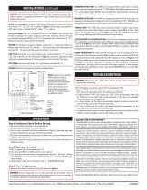
CAUTION-The control board signal common is not at ground potential. Any external signal or equipment connected to the control must be electrically isolated from ground. INSTALLATION, continued SPEED POTENTIOMETER-Connect a 10K Ohm potentiometer (included with control) to terminals "S1", "S2", and "S3" as shown in Figure 4. Alternatively, an isolated 0-5 VDC signal may be connected to "S2" using "S1" as common. Wiring the Speed Pot-Turn the wiper to the full CW position and measure the resistance between the center terminal and the end terminals. Connect the end terminal that measures 0 Ohms to...
Open the catalog to page 2All BODINE ELECTRIC COMPANY catalogs and technical brochures
 Type ABL-3905 and ABL-3907
24 Pages
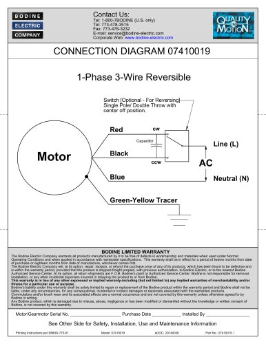 1-Phase 3-Wire Reversible
2 Pages
 Brushless DC Motor Control
24 Pages
 Type ABL-3906C Low-Voltage
20 Pages
 Models 0790 & 079
2 Pages
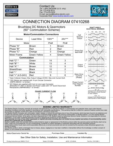 CONNECTION DIAGRAM 07410268
2 Pages
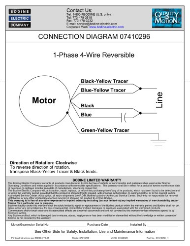 1-Phase 4-Wire Reversible
2 Pages
 STANDARD PRODUCTS 2025
52 Pages
 Bodine Electric Handbook
252 Pages


Archived catalogs
 PLANETARY BLDC GEARMOTORS
2 Pages
 IP-69K
2 Pages
 IP-66
2 Pages
 42R-5L/H
2 Pages
 33A7-WX
2 Pages
 34B-WX , 33A-WX
2 Pages
 42R-FX AC Gearmotor
2 Pages
 2998
2 Pages
 STANDARD PRODUCTS 2024
52 Pages






- Electromotor
- Synchronous motor
- Bodine Electric gear-motor
- Electromotor for industrial applications
- EC motor
- Bodine Electric DC gear-motor
- Compact electromotor
- Permanent magnet motor
- Bodine Electric AC gear-motor
- Industrial electric gearmotor
- Bodine Electric right angle gear-motor
- Motor controller
- Bodine Electric 24 V gear-motor
- Bodine Electric gear train gear-motor
- Planetary gearmotor
- Bodine Electric compact gear-motor
- 12 V electric gearmotor
- Bodine Electric low-noise gear-motor
- Bodine Electric parallel-shaft gear-motor