
- Catalogs
- BODINE ELECTRIC COMPANY
- Filtered PWM Speed Control for Permanent Magnet DC Motors


- Company
- Products
- Catalogs
- News & Trends
- Exhibitions
Filtered PWM Speed Control for Permanent Magnet DC Motors
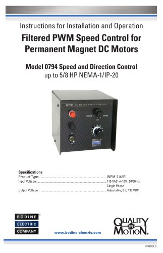
Filtered PWM Speed Control for Permanent Magnet DC Motors
The Bodine Model 0794 speed control is designed for variable speed control of permanent magnet DC motors, featuring adjustable acceleration and deceleration for soft start applications. It is easy to install and operate with simple trim pot adjustments. Key specifications include:
- Product Type: WPM-2148E1
- Input Voltage: 115 VAC +/-10%, 50/60 Hz, Single Phase
- Output Voltage: Adjustable, 0 to 130 VDC
- Max. Motor HP Rating: 5/8 HP for motors rated 2500 RPM @ 130 VDC
- Operating Temperature: 0°C to +40°C
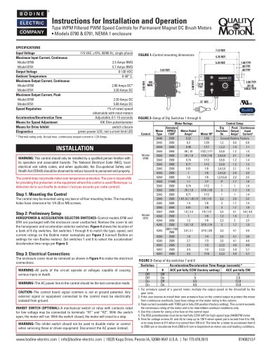
Installation should be performed by qualified personnel. Key steps include mounting the control using appropriate holes, setting motor size selector switches with DIP switches, and ensuring all electrical connections are made with power off, using a fuse sized 1.2 times the motor current rating.
Before starting, verify all connections and settings. Key operational steps include ensuring the motor is securely mounted, adjusting speed using the speed pot, and using non-metallic tools for internal adjustments such as minimum/maximum speed, torque limit, and acceleration/deceleration time.
If issues arise, disconnect the control from AC power and wait seven minutes before checking diagnostic LEDs. If the green "PWR" LED is off, the control is not receiving power. If both "PWR" and "LMT" LEDs are on, ensure the TORQ pot is not fully counterclockwise. Replace blown fuses after reducing the load. Persistent issues should be referred to a Bodine Authorized Service Center.
Bodine Electric Company provides a warranty for products free of defects under normal conditions. The warranty period is 24 months from purchase or 30 months from manufacture for Bodine motors used with Bodine controls, and 12 months when used with non-Bodine controls. The warranty covers repair, replacement, or refund for defective products within the period, excluding incidental expenses and normal wear.
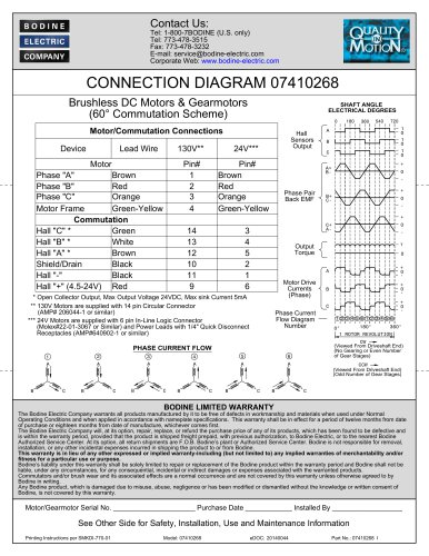
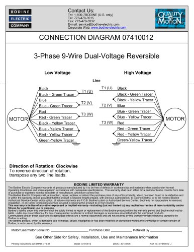
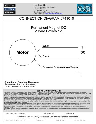
The document describes the connection and operation of a Bodine DC motor. Connecting the control's positive output to the white wire (A2) and the negative to the black wire (A1) results in clockwise motor rotation. In the "STOP" position, a 100 Ohm, 10W braking resistor is used for dynamic braking. In the "REVERSE" position, connections are reversed for counterclockwise rotation.
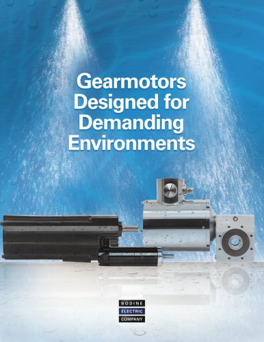
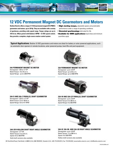
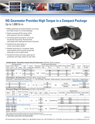
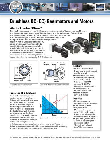
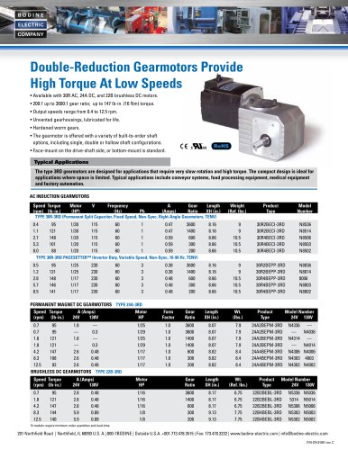
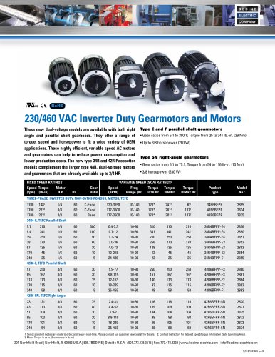
Bodine offers a wide range of variable-speed AC, permanent magnet DC, and brushless DC fractional horsepower gearmotors and motors. For specifications, CAD drawings, or orders, visit their website.
Catalog excerpts
Instructions for Installation and Operation Filtered PWM Speed Control for Permanent Magnet DC Motors Model 0794 Speed and Direction Control up to 5/8 HP NEMA-1/IP-20
Open the catalog to page 1
This manual contains the basic information needed to install and operate Bodine Model 0794 DC Speed Control. This manual does not profess to cover all details or variations in equipment, or to provide for every possible contingency associated with installation, operation, or maintenance. No warranty of fitness for purpose is expressed or implied. Should further information be desired or should particular problems arise which are not covered sufficiently for the user’s purpose, the matter should be referred to the Bodine Electric Company. Read this manual completely and carefully. Pay special...
Open the catalog to page 2
SPECIFICATIONS. . . . . . . . . . . . . . . . . . . . . . . . . . . . . . . . . . . . . . . . . . . . . . . . . . . . . . . 4 INSTALLATION. . . . . . . . . . . . . . . . . . . . . . . . . . . . . . . . . . . . . . . . . . . . . . . . . . . . . . . . . 4 Step 1–Mounting the Control. . . . . . . . . . . . . . . . . . . . . . . . . . . . . . . . . . . . . . . . . . 5 Step 2–Preliminary Setup . . . . . . . . . . . . . . . . . . . . . . . . . . . . . . . . . . . . . . . . . . . . 6 Step 3–Electrical Connections. . . . . . . . . . . . . . . . . . . . . . . . . . . . . . . . . . . . . . . . . 7 OPERATION....
Open the catalog to page 3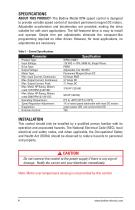
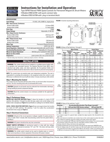
ABOUT THIS PRODUCT-The Bodine Model 0794 speed control is designed to provide variable speed control of standard permanent magnet DC motors. Adjustable acceleration and deceleration are provided, making the drive suitable for soft start applications. The full-featured drive is easy to install and operate. Simple trim pot adjustments eliminate the computer-like programming required on other drives. However, for most applications, no adjustments are necessary. Table 1 - Control Specifications This control should only be installed by a qualified person familiar with its operation and associated...
Open the catalog to page 4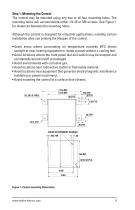
Step 1: Mounting the Control The control may be mounted using any two or all four mounting holes. The mounting holes will accommodate either 1/4-20 or M6 screws. See Figure 1 for distances between the mounting holes. Although the control is designed for industrial applications, avoiding certain installation sites can prolong the lifespan of the control. • Avoid areas where surrounding air temperature exceeds 40ºC (direct sunlight or near heating equipment or inside a panel without a cooling fan). • Avoid locations where the front panel dial and switch may be bumped and accidentally turned on/off...
Open the catalog to page 5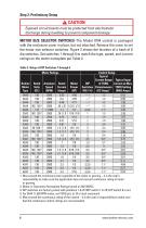
Step 2: Preliminary Setup MOTOR SIZE SELECTOR SWITCHES-The Model 0794 control is packaged with the enclosure cover in place, but not attached. Remove the cover to set the motor size selector switches. Figure 2 shows the location of a bank of 8 dip switches. Set switches 1 through 6 to match the type, speed, and current ratings on the motor nameplate per Table 2. Table 2-Setup of DIP Switches 1 through 6 Motor Ratings Control Setui May exceed the continuous load capability of the motor or gearing - it is the user's responsibility to make sure the application does not exceed continuous rating of...
Open the catalog to page 6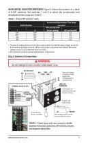
ACCEL/DECEL SELECTOR SWITCHES–Figure 2 shows the location of a bank of 8 DIP switches. Set switches 7 and 8 to select the acceleration and deceleration time range per Table 3. TABLE 3 – Setup of DIP switches 7 and 8. Acceleration/Deceleration Time Range (seconds)1 ACC pot fully CCW (factory setting) ACC pot fully CW 0.1 0.3 0.5 2.0 3.5 12.0 4.0 15.0 1. T he time for voltage across A1 and A2 to ramp up from 0 to 130 VDC when voltage across S1 & S2 switches instantly from 0 to 5 VDC; or the time to ramp down from 130 to 0 VDC when voltage across S1 & S2 switches from 5 to 0 VDC. 2. DIP switches...
Open the catalog to page 7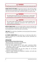
The AC power line to the control should be the very last connection made. INHIBIT SWITCH (OPTIONAL)–A mechanical switch or relay with low voltage contacts may be connected to 0.25” spade terminals “H1” and “H2”. The motor will run with the switch open. Closing the switch will stop the motor. ! The inhibit switch should not be used to disable motor or control when servicing these or driven equipment. Disconnect AC power instead. ! The control board signal common is not at ground potential. Any external signal or equipment connected to the control must be electrically isolated from ground. MOTOR...
Open the catalog to page 8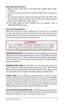
Step 5: Operating the Control 1. With AC power switch OFF, set the speed pot to ZERO (fully counterclockwise). 2. Turn the AC power switch ON. If an optional inhibit switch is being used, open it. 3. Turn speed pot until motor rotates at desired speed. Note that “SCR rated” motors (motors rated at 90 VDC) will run faster with a filtered control because of the 130 VDC max. output voltage. 4. If the motor does not start promptly and run smoothly, refer to “TROUBLESHOOTING” below. Step 6: Internal Adjustments Most users will find the factory settings of the control to be acceptable for their application....
Open the catalog to page 9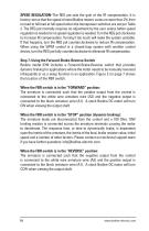
SPEED REGULATION–The REG pot sets the gain of the IR compensation. It is factory-set so that the speed of most Bodine motors varies no more than 2% from no load to full load at full speed when the horsepower switches are set per Table 2. The REG pot normally requires no adjustment by the user unless better speed regulation is needed or no speed regulation is needed. Turn the REG pot clockwise to increase IR compensation. Turning it too much will make the system unstable. If that happens, turn the REG pot counterclockwise to reduce IR compensation. When using the WPM control in a closed-loop system...
Open the catalog to page 10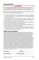
Disconnect the control from the AC power source and wait seven minutes before working on the control, motor, or driven equipment. If the motor does not operate, first carefully remove the enclosure cover and observe the condition of the two diagnostic LEDs. 1. If the green “PWR” LED is not illuminated, the control is not getting power from the AC line. Turn the ON/OFF switch off and double check all connections and fuses. 2. If both the green “PWR” LED and the red “LMT” LED are illuminated, make sure the TORQ pot is not turned fully counterclockwise. If the motor is overloaded, reduce the load...
Open the catalog to page 11All BODINE ELECTRIC COMPANY catalogs and technical brochures
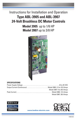 Type ABL-3905 and ABL-3907
24 Pages
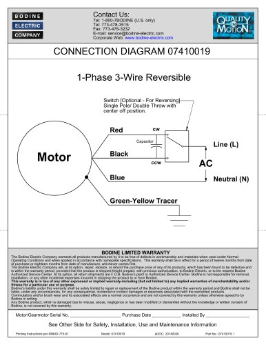 1-Phase 3-Wire Reversible
2 Pages
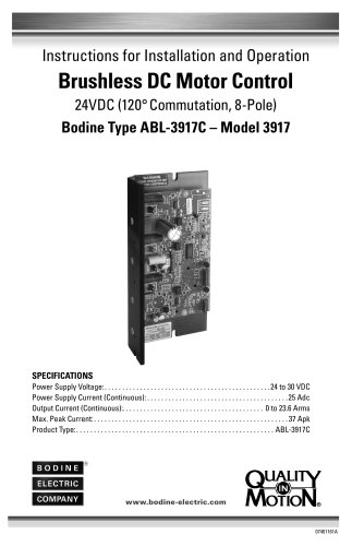 Brushless DC Motor Control
24 Pages
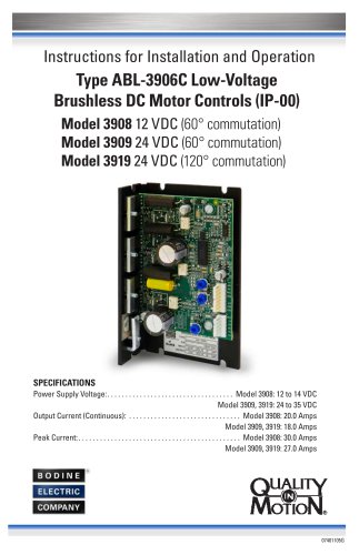 Type ABL-3906C Low-Voltage
20 Pages
 Models 0790 & 079
2 Pages
 CONNECTION DIAGRAM 07410268
2 Pages
 1-Phase 4-Wire Reversible
2 Pages
 STANDARD PRODUCTS 2025
52 Pages
 Bodine Electric Handbook
252 Pages

Archived catalogs
 PLANETARY BLDC GEARMOTORS
2 Pages
 IP-69K
2 Pages
 IP-66
2 Pages
 42R-5L/H
2 Pages
 33A7-WX
2 Pages
 34B-WX , 33A-WX
2 Pages
 42R-FX AC Gearmotor
2 Pages
 2998
2 Pages
 STANDARD PRODUCTS 2024
52 Pages






- Electromotor
- Synchronous motor
- Bodine Electric gear-motor
- Electromotor for industrial applications
- EC motor
- Bodine Electric DC gear-motor
- Compact electromotor
- Permanent magnet motor
- Bodine Electric AC gear-motor
- Industrial electric gearmotor
- Bodine Electric right angle gear-motor
- Motor controller
- Bodine Electric 24 V gear-motor
- Bodine Electric gear train gear-motor
- Planetary gearmotor
- Bodine Electric compact gear-motor
- 12 V electric gearmotor
- Bodine Electric low-noise gear-motor
- Bodine Electric parallel-shaft gear-motor