
- Catalogs
- BODINE ELECTRIC COMPANY
- Brushless DC Motor Controls (IP-00)


- Company
- Products
- Catalogs
- News & Trends
- Exhibitions
Brushless DC Motor Controls (IP-00)

Brushless DC Motor Controls (IP-00)
The Bodine ABL-3906C Low-Voltage Brushless DC Motor Control is compatible with 12 VDC or 24 VDC power supplies. It supports continuous output currents of 20.0 Amps for Model 3908 and 18.0 Amps for Models 3909 and 3919. Key features include electronic commutation, phase current switching, adjustable speed settings, torque, acceleration/deceleration times, and a Smart Reverse™ circuit to prevent plug reversing.
The document highlights the potential hazards of electric motors and stresses the importance of proper design, selection, installation, and use. The ABL-3906C control is UL recognized and RoHS compliant. Users should read the manual thoroughly and follow safety alerts to prevent injury or property damage.
Installation should be conducted by qualified personnel, adhering to NEC, local electrical codes, and OSHA guidelines. The control should be mounted vertically for optimal airflow, and the power supply should be the last connection made to prevent accidental start-up.
Instructions are provided for making electrical connections between the control, motor, and other electronics. Users are responsible for interface leads, and motor phase connections should be kept short to minimize voltage losses. Appropriate fuses should be used to protect the control and motor.
Preliminary checks are necessary before operation. The control allows for speed regulation with a 2% variance at 2500 RPM and a speed range of 25:1. Speed can be controlled using an external potentiometer, an analog input voltage, or the on-board potentiometer.
The document includes a troubleshooting section to address common operational issues.
The warranty section outlines the terms and conditions under which the product is covered, including a 24-month warranty from purchase or 30 months from manufacture for products used with Bodine controls.
The document details the setup and operation of the ABL-3906C motor control system, specifying a 0-5 VDC signal for motor speed control. The system can be integrated into larger control systems using a microprocessor or PLC with a digital to analog converter.
1. External Speed Control: Apply a 0-5 VDC signal across VIN and COM terminals.
2. On-board Trim Potentiometer: Use the MX potentiometer for infrequent speed adjustments, with a jumper across VRF and VIN.
Manual switches, relays, or logic signals can control motor braking, enable, and direction. The document provides a pin-out of the interface connector J4 and logic input conditions.
The control provides a digital tachometer output for monitoring motor speed, with a 5 VDC pulse and 12 pulses per motor revolution. An external filter is needed for an analog voltage tachometer signal.
The control requires a 12 VDC or 24 VDC power source with a minimum capacitance of 5000 μfd. Proper wire sizing is crucial to maintain voltage levels.
Before operation, check all connections and ensure proper mounting and alignment. The motor should be tested unloaded initially. If issues arise, consult troubleshooting guidelines.
Adjustments for maximum speed, torque, and acceleration can be made using trim potentiometers, with detailed instructions provided.
- Motor Not Running: Check voltage, brake switch, enable switch, commutation angle, motor phase connections, and commutation sensor connector. Adjust torque pot if necessary.
- Motor Runs at Full Speed Only: Verify speed signal connection, replace defective speed potentiometer, and remove incorrect jumpers.
- Motor Won't Reach Desired Speed: Adjust maximum speed limit potentiometer, increase speed setting, adjust torque pot, reduce load, or replace power supply if needed.
- Unstable Speed: Correct mechanical alignment, increase speed setting, or replace motor with a higher gear ratio model.
- Speed Maintenance Issues: Adjust torque pot, replace power supply, or reduce load.
Bodine Electric Company offers a warranty for products free of defects in workmanship and materials, covering repair, replacement, or refund, excluding incidental expenses.
Bodine provides a wide selection of variable-speed AC, permanent magnet DC, and brushless DC fractional horsepower gearmotors and motors. For specifications and orders, visit their website.
Catalog excerpts

Instructions for Installation and Operation Type ABL-3906C Low-Voltage Brushless DC Motor Controls (IP-00) Model 3908 12 VDC (60° commutation) Model 3909 24 VDC (60° commutation) Model 3919 24 VDC (120° commutation) SPECIFICATIONS Power Supply Voltage: . . . . . . . . . . . . . . . . . . . . . . . . . . . . . . . . . . . Model 3908: 12 to 14 VDC Model 3909, 3919: 24 to 35 VDC Output Current (Continuous): . . . . . . . . . . . . . . . . . . . . . . . . . . . . . . . . Model 3908: 20.0 Amps Model 3909, 3919: 18.0 Amps Peak Current: . . . . . . . . . . . . . . . . . . . . . . . . . . . . . . . . . . . . . . . . . . . . . Model 3908: 30.0 Amps Model 3909, 3919: 27.0 Amps
Open the catalog to page 1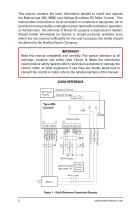
This manual contains the basic information needed to install and operate the Bodine type ABL-3906C Low-Voltage Brushless DC Motor Control. This manual does not profess to cover all details or variations in equipment, nor to provide for every possible contingency associated with installation, operation, or maintenance. No warranty of fitness for purpose is expressed or implied. Should further information be desired or should particular problems arise which are not covered sufficiently for the user’s purpose, the matter should be referred to the Bodine Electric Company. IMPORTANT Read this manual...
Open the catalog to page 2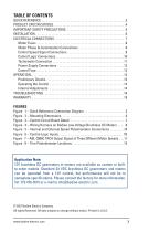
QUICK REFERENCE . . . . . . . . . . . . . . . . . . . . . . . . . . . . . . . . . . . . . . . . . . . . . . . . . . . . . 2 PRODUCT SPECIFICATIONS. . . . . . . . . . . . . . . . . . . . . . . . . . . . . . . . . . . . . . . . . . . . . . 4 IMPORTANT SAFETY PRECAUTIONS. . . . . . . . . . . . . . . . . . . . . . . . . . . . . . . . . . . . . . 5 INSTALLATION. . . . . . . . . . . . . . . . . . . . . . . . . . . . . . . . . . . . . . . . . . . . . . . . . . . . . . . . . 6 ELECTRICAL CONNECTIONS. . . . . . . . . . . . . . . . . . . . . . . . . . . . . . . . . . . . . . . . . . . . . 7 Motor Fuses...
Open the catalog to page 3
PRODUCT SPECIFICATIONS The Type ABL-3906C Low-Voltage Brushless DC Motor Control is a chassis type, designed to be mounted in a separate enclosure supplied by the user. It operates from a DC power supply or from a battery (12 VDC or 24 VDC, depending on the control model). The controls provide the necessary electronic commutation and phase current switching to operate Bodine lowvoltage brushless DC motors. Speed can be controlled by an external or onboard MAX speed trim potentiometer, or a 0 to 5 VDC analog input signal. Other features include adjustable maximum speed settings, torque, and acceleration...
Open the catalog to page 4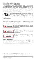
IMPORTANT SAFETY PRECAUTIONS “The use of electric motors and generators, like that of all other utilization of concentrated power, is potentially hazardous. The degree of hazard can be greatly reduced by proper design, selection, installation, and use, but hazards cannot be completely eliminated. The reduction of hazard is the joint responsibility of the user, the manufacturer of the driven or driving equipment, and the manufacturer of the motor or generator.”* The Bodine type ABL-3906C control was evaluated by Underwriters Laboratories (UL) for compliance to UL standard 508 and CSA standard...
Open the catalog to page 5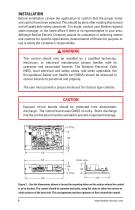
Before installation, review the application to confirm that the proper motor and control have been selected. This should be done after reading this manual and all applicable safety standards. If in doubt, contact your Bodine regional sales manager, or the home office if there is no representative in your area. Although Bodine Electric Company assists its customers in selecting motors and controls for specific applications, determination of fitness for purpose or use is solely the customer’s responsibility. ! This control should only be installed by a qualified technician, electrician, or electrical...
Open the catalog to page 6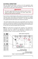
ELECTRICAL CONNECTIONS Read the following instructions as well as all of the applicable safety recommendations, before making any electrical connections between the control, motor, or other motion control electronics. ! The power supply should be the last connection made in order to prevent accidental start-up. Disconnect the power supply before making any other electrical connections. Figure 3 shows a detailed diagram of the control circuit board and the various connection points. Stock Bodine 24-Volt Brushless DC motors are supplied with commutation leads terminated at connector J1. The motor...
Open the catalog to page 7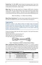
Control Fuse: The ABL-3906C control should be protected with a fuse in the positive power supply lead. The fuse should be sized to allow the motor to run at full speed and load with a safety margin. Motor Fuse: The Fuse type should be UL Category JDYX2 with a maximum rating of 25A. The user should install a fuse in two of the three motor phase connections, as shown in Figure 1. The value of the fuse is dependent on the current rating of the motor. Determine the fuse value using the following formula: Motor Fuse Rating = 1.2 x Motor Current Rating Motor Phase Connections: The motor phase outputs...
Open the catalog to page 8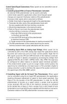
Control Speed Signal Connections: Motor speed can be controlled in one of three ways: 1. ontrolling Speed With an External Potentiometer (included): C An external 10 KΩ potentiometer can be used to externally control motor speed (for applications where more frequent speed changes are required). Clockwise rotation of the potentiometer increases motor speed, when connected as follows: a. older three leads of appropriate length to the potentiometer. S b. erminate the other ends of the potentiometer leads with T the pins supplied with the 8-pin interface connector. c. ount the potentiometer in the...
Open the catalog to page 9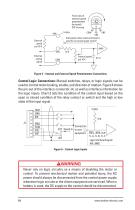
Front view of external speed potentiometer (included) CW increase 5 Volts VIN Add jumper when internal trimpot is used for on-board speed control VIN External analog signal Figure 5 – Internal and External Speed Potentiometer Connections Control Logic Connections: Manual switches, relays, or logic signals can be used to control motor braking, enable, and direction of rotation. Figure 6 shows the pin-out of the interface connector J4, as well as interface information for the logic inputs. Chart 3 lists the condition of the control input based on the open or closed condition of the relay contact...
Open the catalog to page 10All BODINE ELECTRIC COMPANY catalogs and technical brochures
 STANDARD PRODUCTS 2025
52 Pages
 Bodine Electric Handbook
252 Pages

Archived catalogs
 PLANETARY BLDC GEARMOTORS
2 Pages
 IP-69K
2 Pages
 IP-66
IP-662 Pages
 42R-5L/H
2 Pages
 33A7-WX
2 Pages
 34B-WX , 33A-WX
2 Pages
 42R-FX AC Gearmotor
2 Pages
 2998
29982 Pages
 STANDARD PRODUCTS 2024
52 Pages






- Synchronous motor
- Multipole motor
- Bodine Electric gear-motor
- EC motor
- Electromotor for industrial applications
- 24 V motor
- Bodine Electric DC gear-motor
- 4-pole motor
- Compact electromotor
- Permanent magnet motor
- Industrial electric gearmotor
- Bodine Electric right angle gear-motor
- Bodine Electric AC gear-motor
- Motor controller
- Bodine Electric 24 V gear-motor
- Solid-shaft gear-motor
- Planetary gearmotor
- Bodine Electric gear train gear-motor