
- Catalogs
- BODINE ELECTRIC COMPANY
- Brushless DC Motor Control


- Company
- Products
- Catalogs
- News & Trends
- Exhibitions
Brushless DC Motor Control
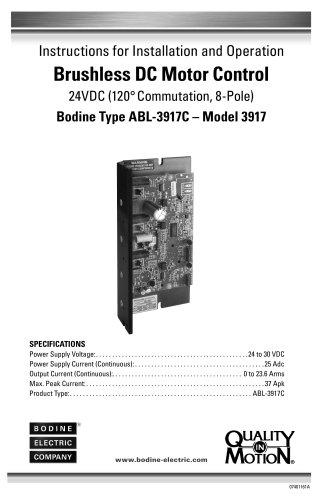
Brushless DC Motor Control
The Bodine ABL-3917C Brushless DC Motor Control operates with a 24 to 30 VDC power supply, supporting a continuous current of up to 25 Amps and a peak current of 37 Amps. It offers a speed regulation of 2% at 2500 RPM and a speed range of 25:1 at rated load. The control uses Pulse Width Modulation (PWM) at 20 kHz and allows adjustments for maximum speed, torque, and acceleration.
General Information
This manual provides installation and operation instructions, emphasizing safety standards and compliance with ANSI, NEMA, UL, and CSA standards.
Control Description and Features
The ABL-3917C is a low-voltage control for Bodine brushless DC motors, featuring electronic commutation, phase current switching, and a Smart Reverse™ circuit. Speed control options include an external potentiometer, on-board trim potentiometer, or a 0 to 5 VDC analog input.
Important Safety Precautions
Adherence to safety precautions is crucial to prevent hazards. Proper grounding, enclosure selection, and maintenance are essential. The control is optimized for Bodine motors and should not be used with other brands without consultation.
Installation Instructions
Installation involves mounting the control, making electrical connections, and configuring motor power and commutation sensor connections. Speed control can be managed through various methods.
Operating Instructions
Preliminary checks are necessary before operation. The control allows internal adjustments to maximum speed, acceleration, and torque limits.
Troubleshooting and Warranty
The manual includes troubleshooting guidance and warranty information, stressing the importance of using the control within specified conditions.
Ventilated Products
Open, ventilated products are for clean, dry environments with unrestricted airflow. Avoid inserting objects into ventilation openings.
Servicing
Only authorized Bodine service representatives should perform repairs. Unauthorized repairs void the warranty. Repairs should involve replacing the entire printed circuit board assembly. For servicing, return the control to Bodine Electric Company or an Authorized Distributor.
Installation Instructions
Mounting the Control: Preferably mount vertically, but non-vertical mounting is acceptable if ambient temperature does not exceed 75°C. Use heat sink slots for optimal airflow.
Electrical Connections: Only qualified personnel should install the control, adhering to NEC and local safety codes. Provide a proper enclosure and avoid working on or near the control while connected to power.
Motor Power Connections
Motor phase outputs are labeled A, B, and C. Minimize wire length to reduce voltage drop. Use 10 AWG wire for power connections and ensure all wiring is rated for at least 95°C.
Speed Control
Motor speed can be controlled via an external 10 KΩ potentiometer, a 0 to 5 VDC analog input signal, or the on-board speed potentiometer.
Control Inputs
Manual switches, relays, or logic signals can control motor braking, enable, and direction of rotation. A digital tachometer output is available for monitoring motor speed.
Power Supply Connections
The control requires a 24V regulated power supply with sufficient current capacity, connected using 1/4 inch quick disconnect terminals.
Operating Procedures
1. Disconnect AC power before starting operations. Ensure the speed potentiometer is set to zero and switches are open.
2. Connect AC power and set the direction switch.
3. Adjust the speed potentiometer to start the motor.
4. If issues arise, check connections and fuses, and refer to troubleshooting guidelines.
Internal Adjustments
- Use the MAX speed trim potentiometer to set motor speed.
- Adjust acceleration time using trim potentiometer R21.
- Set torque/current limit using the TORQUE trim potentiometer, ensuring it does not exceed 200% of the motor's current rating.
Troubleshooting
- If the control blows a line fuse, check for incorrect power supply, excessive voltage, or shorted leads.
- If the motor does not start, verify power supply, check for overloads, and ensure all connections are secure.
- For unstable motor speed, check alignment, compatibility, and potentiometer settings.
Warranty Information
Bodine products are warranted to be free from defects for 24 months with Bodine controls, or 12 months with non-Bodine controls. Warranty claims require proof of purchase and prior authorization for returns.
Contact Information
For assistance, contact Bodine Electric Company at 773-478-3515 or [email protected].
Catalog excerpts
Instructions for Installation and Operation Brushless DC Motor Control 24VDC (120° Commutation, 8-Pole) Bodine Type ABL-3917C – Model 3917 SPECIFICATIONS Power Supply Voltage: . . . . . . . . . . . . . . . . . . . . . . . . . . . . . . . . . . . . . . . . . . . . . . 24 to 30 VDC Power Supply Current (Continuous): . . . . . . . . . . . . . . . . . . . . . . . . . . . . . . . . . . . . . . . 25 Adc Output Current (Continuous):. . . . . . . . . . . . . . . . . . . . . . . . . . . . . . . . . . . . . . . . 0 to 23.6 Arms Max. Peak Current: . . . . . . . . . . . . . . . . . . . . . . . . . . . . . . . . . . . . . . . . . . . . . . . . . . . . . . 37 Apk Product Type: . . . . . . . . . . . . . . . . . . . . . . . . . . . . . . . . . . . . . . . . . . . . . . . . . . . . . . . . ABL-3917C
Open the catalog to page 1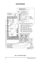
QUICK REFERENCE ENLARGED VIEW OF CONTROL INPUTS (Page 12-15) 0 - 5 VDC Analog Power Source Shielded Cable 24V Regulated Power Supply INTERNAL ADJUSTMENTS (Page 18) TORQ: Adjust motor torque limit. CW increases torque limit. ACCEL: Adjust motor acceleration response time. CW increases time. MAX: Adjust (or ”scale”) maximum motor speed. CW increases speed. Optional Normally Closed (N.C.) thermal switch (TAK and LMT output details on page 14 & 15) Current Limit Out Tachometer Out Supply Common Supply Fuse (page 16) COMMUTATION WIRE COLORS J1 COMMUTATION SENSOR INPUTS (Page 11) STANDARD MODELS COM...
Open the catalog to page 2
Control Input Fuse Calculation 16 © 2022 Bodine Electric Company. All rights Reserved. All data subject to change without notice . Printed in U . S . A.
Open the catalog to page 3
GENERAL INFORMATION Thank you for selecting a Bodine type ABL-3917C Series Low-Voltage Brushless DC Motor Control. Your new control will provide the same excellent performance and reliability that have been a Bodine tradition since 1905. Bodine Electric Company takes pride in the quality of its products and in satisfying its customers. Every effort has been made to provide you with a product free of defects in design, workmanship, and materials. In order for us to maintain our tradition of quality, please report any cases of unsatisfactory service or products to Bodine Electric Company promptly....
Open the catalog to page 4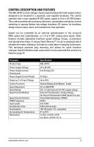
The ABL-3917C is a low-voltage, chassis-type brushless DC motor speed control, designed to be mounted in a separate, user-supplied enclosure . The control operates from a user-supplied 24 VDC power supply or from a 24 VDC battery. This control provides the necessary electronic commutation and phase current switching to operate Bodine low-voltage brushless DC motors . Its brushless design assures quiet, clean, and maintenance-free operation . Speed can be controlled by an external potentiometer or the on-board MAX speed trim potentiometer, or a 0 to 5 VDC analog input signal . Other features include...
Open the catalog to page 5
IMPORTANT SAFETY PRECAUTIONS The following safety precautions must be observed during all phases of installation, operation, service, and repair of this control. Failure to comply with these precautions or with specific warnings elsewhere in this manual violates safety standards of design, manufacture and intended use of the product. Bodine Electric Company assumes no liability for the customer’s failure to comply with safety requirements and practices. The use of electric motors and gearmotors, like that of all utilization of concentrated power, is potentially hazardous. The degree of hazard...
Open the catalog to page 6
Inspecting the Control Check the items you received against your purchase order. Carefully examine the control (and any optional kits or parts) for shipping damage. Report parts errors to Bodine. Shipping damage claims should be made to the freight carrier. Before installation, review the application to confirm that the proper motor and control have been selected. This should be done after reading this manual and all applicable safety standards. If in doubt, contact your Bodine representative, or the home office if there is no representative in your area. Although Bodine Electric Company assists...
Open the catalog to page 7
Ventilated Products Open, ventilated products are suitable for clean, dry locations where cooling air is not restricted. Do not insert anything into a product’s ventilation openings. Servicing Emergency field repairs must be made only by authorized Bodine service representatives. Repairs made by persons not authorized by the Bodine Electric Company will void the warranty. Field repairs must be limited to replacing the entire printed circuit board assembly. Because of the danger of introducing safety hazards, do not install substitute parts or perform any unauthorized modifications to electronic...
Open the catalog to page 8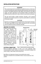
INSTALLATION INSTRUCTIONS WARNING This control should only be installed by a qualified technician, electrician, or electrical maintenance person familiar with its operation and associated hazards. The National Electrical Code (NEC), local electrical and safety codes, and when applicable, the Occupational Safety and Health Act (OSHA) should be observed to reduce hazards to personnel and property. The user must provide a proper enclosure. Circuitry is not at ground potential. Do not perform work on or near the control while it is connected to the power supply. Exposed circuit boards should be protected...
Open the catalog to page 9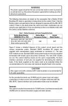
The power supply should be the last connection made in order to prevent accidental start-up. Disconnectthe power supply before making any other electrical connections. The following instructions are based on the assumption that a Bodine 24-Volt Brushless DC motor or gearmotor is being driven by the control . Chart 1 lists the Bodine motors and gearmotors that are designed to operate with the ABL-3917C control . If there is any doubt about the control and motor combination you are using for your application or if you are planning to drive a non-Bodine motor with the control, contact Bodine in...
Open the catalog to page 10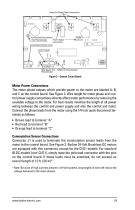
Output For Motor Power Connections Acceleration/Deceleration Power Supply Trim Potentiometer Connections Commutation Sensor Inputs Control Inputs MAX Speed Trim TORQ Trim Potentiometer Potentiometer Figure 3 – Control Circuit Board Motor Power Connections The motor phase outputs which provide power to the motor are labeled A, B, and C on the control board. See Figure 3. Wire length for motor phase and control power supply connections directly affect motor performance by reducing the available voltage to the motor. For best results minimize the length of all power wiring between the control and...
Open the catalog to page 11All BODINE ELECTRIC COMPANY catalogs and technical brochures
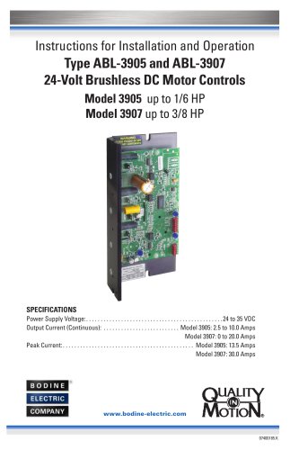 Type ABL-3905 and ABL-3907
24 Pages
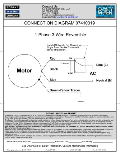 1-Phase 3-Wire Reversible
2 Pages
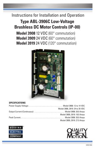 Type ABL-3906C Low-Voltage
20 Pages
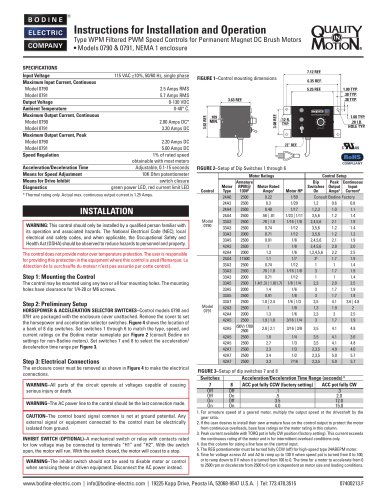 Models 0790 & 079
2 Pages
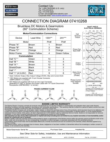 CONNECTION DIAGRAM 07410268
2 Pages
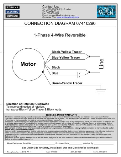 1-Phase 4-Wire Reversible
2 Pages
 STANDARD PRODUCTS 2025
52 Pages
 Bodine Electric Handbook
252 Pages

Archived catalogs
 PLANETARY BLDC GEARMOTORS
2 Pages
 IP-69K
2 Pages
 IP-66
2 Pages
 42R-5L/H
2 Pages
 33A7-WX
2 Pages
 34B-WX , 33A-WX
2 Pages
 42R-FX AC Gearmotor
2 Pages
 2998
2 Pages
 STANDARD PRODUCTS 2024
52 Pages






- Synchronous motor
- Bodine Electric gear-motor
- Electromotor for industrial applications
- EC motor
- Bodine Electric DC gear-motor
- Compact electromotor
- Permanent magnet motor
- Bodine Electric AC gear-motor
- Industrial electric gearmotor
- Bodine Electric right angle gear-motor
- Motor controller
- Bodine Electric 24 V gear-motor
- Bodine Electric gear train gear-motor
- Planetary gearmotor
- Bodine Electric compact gear-motor
- 12 V electric gearmotor
- Bodine Electric low-noise gear-motor
- Bodine Electric parallel-shaft gear-motor